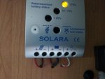
Solar charge controller - load terminals - what practical use in a MH ?

  • Thread starter Deleted member 62288
  • Start date
Could you not use the load out put when battery are full to heat water that way it save on gas and provides some use from the spare electricty unles you are like ed on toast who put it into trees for storage till later that what he said at hereford lol
 
Run my fridge cooling fans and controller off my Aux Solar Controller Controller Solar.jpg
 
My load output is connected to all my 12V equipment - lights, fridge, USB sockets etc. The output is 'live' whether or not there is any input from the solar panels. By doing this, I can also monitor how much power I am using, from the data output connection (or via bluetooth). So I can compare how much power I'm using with how much the panels are generating.
Another use of the load output is to prevent the batteries discharging too much. More details here, scroll down to 'Load Output'.

I think this feature is fairly specific to the Victron MPPT Controller, and then only the ones that have a load connection (most of them don't).
I would also guess you are limited in current draw to the spec of the Controller as well? 15A or 20A maximum? So would have to be careful on what you are running simultaneously.

Neat idea if you are within those specs though.

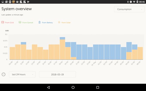
The Victron kit is really nice for monitoring what is going on.
This is a graph of my consumption in the last 24hrs and where the power is coming from (solar or battery)
Screenshot_20180519-084614 by David, on Flickr
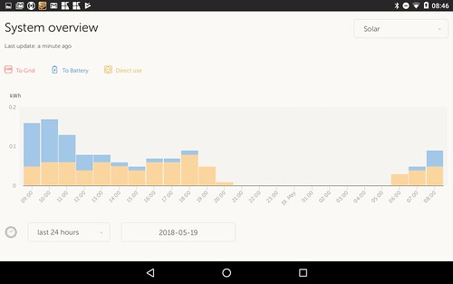
And same time period, showing what the solar has harvested and how it is being used
Screenshot_20180519-084637 by David, on Flickr
 
Forgive my ignorance.
Does not keep switching power to the starter battery dull the life of that battery as you making a signature of drop to 90% and I charge to 100%?or can you set the discharge limit before charging?

Not sure that I understand your question.

I've configured my MPPT controller to ignore the EBL and hence the engine battery is not in my equation. (currently)

The MPPT unit is wired directly to the leisure batteries and has excess / spare power that is tapped via the LOAD terminals.

The EBL has a facility on Block 7 to input an "auxilliary charging unit", so I connected the LOAD terminals to here but it seemed ineffective, non-operational (yes, I added a 20A fuse into the EBL designated slot.) to no effect.

I will also try to use the EBL solar input on Block 6 which I know works OK, this should then allow the engine battery to be charged via the EBL off the LOAD terminals / solar excess power..
 
The MPPT unit is wired directly to the leisure batteries and has excess / spare power that is tapped via the LOAD terminals

I might be being stupid here so bear with me

the idea of the load terminals is to be able to use power generated which is in excess to that needed to recharge the battery - is that right?

what is the difference between (for example) charging your laptop from the 'load' terminal and charging it from the battery (which is being charged by the panel)?

surely the net result is the same?

Good question.

the voltage at the load terminals is around 14v with no load, it is raw voltage and not managed as such.
A charger will have a feedback mechanism that adjusts the voltage output depending upon the load being drawn by the battery.
So I would not use this source for charging unless a proper charger was in the circuit.
It is easier to use the existing battery supplied 12v sockets.
Also, the load is not active when there is no sunshine so it is not available 24/7 as the batteries are.

I have a 12v laptop charger that uplifts the output voltage to 18v also a 12v in / 24v out charger for my mobility scooter, either of which can be used by the load terminals, but there is no point in the added complexity and circuits, when I can simply use any of the existing cigar sockets.

It is possible to feed this into the electric 220v element on the hot water tank, but this will only warm up the water to speed up the time taken to heat the water to normal hot temperature, but again, this is complex and inefficient.

My preferred route is to rig the excess power from the solar/mppt load and feed it into the EBL where it be used to keep the engine battery topped up. This is important for me as previous owners have hung accessories onto the engine battery, which depletes it and which currently can't be charged while parked up in the wild.
The engine battery is charged while driving or on a EHU only with my current configuration.

A B2B (battery to battery) charger can be used, but it looks like the EBL can be rigged to do the same thing while saving on the (not inconsiderable) cost of a B2B unit.

But I'm undecided right now,
 
All the MPPT controllers I've had have allowed you to programme when the load terminals are powered.

Perhaps they come on when the sun shines (to use spare power) or when it doesn't shine (to provide light in the dark) or on some sort of timer.

Generally I think they are of little use in a motorhome, but I have a solar setup in an isolated garden, and the load output is used to switch things off at night (regardless of sun situation) and also would switch the load off if the battery voltage fell too low (not going to happen without a major fault!)

I expect that the Vicron is no less programmable than cheaper brands. Hopefully the instructions are less incomprehensible. But I would simply ignore the load terminals in a motorhome setup. More to go wrong = potential problems.

Thanks for that, my mppt controller is not programmable so once the LBs are full, it outputs to the load terminals, it is passive.

I'll try to route the power to the EBL simply for the engine battery as (up to) 20 A is available and going to waste and my engine battery depletes over time spent off-grid and stationary.

I will be moving any after-market loads off the engine battery and onto the leisure batteries to eliminate the drain and if the mppt/load can be routed through the EBL, it will manage the engine batteries while off-grid.

It's mostly research and experiment at this point.

I have a problem: engine battery depletes while parked up, I also have excess power at the load terminals, the challenge is to marry up the problem to the mppt which should be the solution.

Other than this, I agree that on a motorhome, the load terms are pretty redundant otherwise.
 
Not sure what you are trying will work with the EBL or even if you want it to. I ‘think’ that the EBL puts charge to the leisure and starter batteries when charge is going through it, whether that be EHU, Solar or other. I don’t ‘think’ if leisure batteries are full it will pass everything to the starter battery.

It may do what you want but I suspect it will charge ALL batteries and if your solar has cut off because batteries are full you would be forcing an overcharge. I ‘think’ you would need to use a b2b to achieve what you want or split you panels through two controllers maybe so one goes through the EBL and the rest direct to batteries through controller.

I stress I only ‘think’ this so please contact someone who really knows before risking damaging your batteries. I tried to email Udo Lang earlier this year and got no response so not sure if I had email address wrong or he is no longer there, if he is he can tell you.

The matter of a cascade / loop occurred to me, My understanding of the logic followed by the EBL is :

A) Priority 1 is to charge the engine battery from whatever input source is available to the EBL (engine/EHU/Solar/aux charger i/p on block 7)

B Once the engine battery has drunk it's fill, the EBL switches to the Leisure battery bank.

Each of the batteries will have their own and different re-charge needs, the EBL will "read" the battery state and adjust the voltage accordingly.

The EBL will never be charging both at the same time, But the LBs might have 2 devices charging them up at the same time, which is not a problem.

So if I use the existing but not connected optional inputs that are available at the EBL, I should be able to allow the EBL to perform as designed, using either the unused inputs on block 7 or the solar inputs available on block 6., both of which should accept the output of the load terminals.

The batteries will never get cooked or overcharged in this scenario.

It is common practice to connect a solar controller directly to the batteries as well as having a device such as the EBL unit also connected to them.

It is also perfectly acceptable to have BOTH charging at the same time, as each are proper chargers which monitor the battery status and adjust themselves independently of each other.

Anyone with a solar controller connected directly to the leisure batteries will be dual charging while driving on when on a hook-up anyways.


That is my theory which follows the logic in the technical manual of the EBL.

I'm not yet 100% confident in the theory at this point, but I'm up in the 90's with it.

edit: I just read the english manual and was surprised to see that the EBL ONLY charges the leisure batteries when on solar, it never goes near the engine battery. The engine battery is only ever charged from the alternator or the EHU.

So the theory carefully laid out above is actually utter bollox and just a figment of a brain marinated in Sativa.

edit2: well it's not all crap, only my expectation that I could use the load terminals to charge the engine battery THROUGH the EBL, this is wrong and won't work.

So it looks like a battery to battery charger will be needed after all.


james
 
Last edited by a moderator:
Think I got a bit mixed up somewhere, thought you meant feeding from load to the input for an additional charger, that’s the bit that charges leisure and starter batteries.

I do think B2B would be your better option if you need to be charging starter and not usin EBL but all I know is from reading various threads/forums though so better for some who have actually done it to advise 👍
 
I bit the bullet and purchased a Sterling BB1230 B2B unit.

It's not yet sited or fitted.

It's a big-headed, loud object with so much pseudo techie BS printed on almost every exposed surface area,
I don't like loud and pretentious.

Unfortunately, the only place I can install it is on the side wall of the main hab area, in full view at all times.

It's irritating me already, even before it is fitted and operational.

If it doesn't meet my expectations, it's in for a good thrashing.

james
 
The Sterling B2B is designed to go in the engine compartment. The cooling fan is noisy and you won't want it in the inside of the vehicle unless in a cupboard.

Electrically, it is meant to be connected near the starter battery (or the alternator or the starter motor) to reduce voltage drop, in a well-ventilated place. Though with just 30A capacity, the cable length may not matter so much.

The writing on it is informative. If you think it is pseudo techno BS, you need to get someone who understands to translate it for you.

You seem to always like to insert a little dig in your posts, but your comment about siting it in the engine compartment may be a useful suggestion, thanks and I hope that your day gets better for you.

I commented on the external appearance of this item, your derogatory response referred to the technical function of the device and my understanding of what it does. There is a difference between appearance and function, perhaps a level of subtlety that is not appreciated by yourself.

I am not deploying this unit to be fed by the engine alternator, I am deploying it to be fed by the MPPT load terminals, which are in the main habitation area
I'd like to keep it as close as possible to the source of power and it's fuse.

Reference the techie bs plastered all over it, I stand by my comments .
 
Last edited by a moderator:
Sterling make some good kit (although it looks so dated!) and is festooned with writing all over, but I find the most annoying thing about them is Charles Sterlings constant slagging off of any product that doesn't have his name on it :(


FWIW, I know you are installing a B2B charger in order to charge the STARTER Battery from Solar, but the usual purpose of a B2B is of course to install the LEISURE batteries via the Alternator.
For that purpose, I am taking a route you may find of academic interest? Rather then installing a B2B in the usual fashion (the most expensive option), or a typical Split-Charge Relay (the most basic option), I am fitting (when I eventually get round to it) a Programmable Digital Alternator Regulator from Sterling (plus standard 200A Switching Relay).
This will change the alternator output from a basic output to a multi-stage battery charger output, tuned to your particular battery type (which is one reason why I installed an AGM Battery under the bonnet to match the AGMs in the Leisure battery bank when replacing the knackered Starter Battery).
One handy thing about this over a Leisure Battery B2B setup is it will charge the Starter Battery using a multi-stage Battery Charger algorithm as well, not just the Leisure Batteries.


(Going in the other direction, my Solar Controller doesn't have any useable Load outputs as the 'virtual' ones are shared with the comms port I am already using so I will just have a 3-way switch on the Relay control line to allow me to manually spoof the D+ signal from the alternator into the relay so when getting good solar charging, can push some excess wattage over)
 
Once again, you miss the point. The B2B needs to be well-connected to the supply battery. That means it needs to be connected near the battery or near to something with a fat cable to the battery. Basically that means the starter or the alternator.
The solar controller cable will be relatively slight.
It has little to do with the charging power source, everything to do with the connection to the battery.

I think you are missing the point, not me.

There is NO supply battery in my configuration,
There is NO alternator in my configuration.
I am NOT trying to charge the engine battery from the auxiliary batteries, each battery bank is unaware of the other's existence.

The maximum current that is available from the MPPT load terminals to the BB1230 input is 15A.
The maximum current available from the BB1230 to the engine battery is 30A but it will never get to this ceiling as the source will be limited to 15A input.

Your suggestion to re-configure my installation will not meet the objective of "charge the engine battery from the solar/mppt load terminals".

If I followed your suggestion, I would have :

A) The main 40A MPPT output connected to the 95Ah engine battery
and
B) The 15A mppt load terminals connected to the 460Ah leisure batteries via some type of charging device.

In my book, this is a misallocation of resources and is perfectly senseless and 100% incorrect.

The Hymer only charges the engine battery via the Elektroblock. which in turn only charges the engine battery under 2 scenarios:

A) On the move, via the alternator,
and
B) While on an EHU/220v hookup.

Even when using the correct schaudt solar controller, plugged into the EBL, it doesn't charge the engine battery unless A or B above conditions are met.

There is a discrepancy whereas if I park up for any length of time, the engine battery discharges slightly each day with no correspondent re-charge available, while I have spare/excess capacity at the mppt/load terminals.
So to ensure that ALL my batteries get the benefit of free solar charging, I need to fill in this gap.

I could have done this by using a cheap pwm solar controller hooked up to the load terminals and fed to the engine battery, but I went for the sterling loud jobbie instead.

When installations are completed, I will have masses of leisure power available and an automatic re-charge/top-up of the engine battery and the leisure batteries, which will easily provide me with free electric that meets my currently known daily load.

makes perfect sense to me.

james
 
Last edited by a moderator:
I think you are missing the point, not me.

There is NO supply battery in my configuration,
There is NO alternator in my configuration.
I am NOT trying to charge the engine battery from the auxiliary batteries, each battery bank is unaware of the other's existence.

The maximum current that is available from the MPPT load terminals to the BB1230 input is 15A.
The maximum current available from the BB1230 to the engine battery is 30A but it will never get to this ceiling as the source will be limited to 15A input.

Your suggestion to re-configure my installation will not meet the objective of "charge the engine battery from the solar/mppt load terminals".

If I followed your suggestion, I would have :

A) The main 40A MPPT output connected to the 95Ah engine battery
and
B) The 15A mppt load terminals connected to the 460Ah leisure batteries via some type of charging device.

In my book, this is a misallocation of resources and is perfectly senseless and 100% incorrect.

The Hymer only charges the engine battery via the Elektroblock. which in turn only charges the engine battery under 2 scenarios:

A) On the move, via the alternator,
and
B) While on an EHU/220v hookup.

E
ven when using the correct schaudt solar controller, plugged into the EBL, it doesn't charge the engine battery unless A or B above conditions are met.

There is a discrepancy whereas if I park up for any length of time, the engine battery discharges slightly each day with no correspondent re-charge available, while I have spare/excess capacity at the mppt/load terminals.
So to ensure that ALL my batteries get the benefit of free solar charging, I need to fill in this gap.

I could have done this by using a cheap pwm solar controller hooked up to the load terminals and fed to the engine battery, but I went for the sterling loud jobbie instead.

When installations are completed, I will have masses of leisure power available and an automatic re-charge/top-up of the engine battery and the leisure batteries, which will easily provide me with free electric that meets my currently known daily load.

makes perfect sense to me.

james

I used the Schaudt 1218 recommended PWM solar regulator on my last 2 vans and it comes with a wiring kit that takes seconds to fit and will charge the engine battery from solar panels. They did not make an MPPT regulator when I bought mine but I imagine it will do the same.
 
I used the Schaudt 1218 recommended PWM solar regulator on my last 2 vans and it comes with a wiring kit that takes seconds to fit and will charge the engine battery from solar panels. They did not make an MPPT regulator when I bought mine but I imagine it will do the same.

Thanks for your comments.

I had a Schaudt PMW fitted that plugged into the Elecktroblock, but I've just removed it as it does NOT charge the engine battery when parked up. I didn't realise this until I got an English PDF for the EBL.

Not sure which models of schaudt kit you have, but on mine, the engine battery is left unattended when parked up.

So I needed a solution that charged both sets of batteries off the solar panels.

The EBL-100-2 pdf quotes :

Battery charging via solar charge regulator :
Starter battery Charging current Float charge max. 2 A
Battery charging via solar charge regulator Only the living area battery is charged.
Maximum charging current 14 A, fuse-protected by 15 A fuse.

which is confusing and contradictory, but in practical terms, I was not seeing any engine battery charging while stationary unless the EHU was live or the engine was running.

Also the max charge via the 1218 is 14A, which is insufficient to keep the 460Ah leisure batteries charged.

I replaced the 1218 with a Victron MPPT giving me up to 40A to the 460Ah leisure batteries, while also providing me with 2 extra "load" terminals that will be input into the Sterling BB1233 to give me up to 14A solar into the engine battery, from 4 panels on the roof of approx 360 watts.

I thought that this was an elegant, albeit expensive solution. Worth it as I have just spent in excess of £1000 on 2 Victron AGM 20Ah batteries.
 
Last edited by a moderator:
'You had a Schaudt regulator fitted' .... that sounds typical of the Motorhome Leisure industry. Apart from total newbies, the customers know more than the Dealers. :(

Whoever neglected to fit the adaptor was a pillock. :)
 
No, you have totally misunderstood what I suggest.

Your ideas seem ridiculous to me, so as a result my suggestions are totally unhelpful in assisting you need n achieving what you are trying to do. I had assumed you were trying to do something that is completely different. Sorry for my distraction from your chosen path.

Nothing you can do to adapt what I now think you are doing would make it seem a good idea to me.

Perhaps you need to re-read the techno babble about the B2B charger and how it works. If you can't send it back, they fetch a good price secondhand.

I am really and sincerely grateful for constructive comments and suggestions. This is how I continue to learn.
However, you keep giving me suggestions that do not meet my clearly stated objectives, or, as in this instance, you proclaim doom and failure without actually saying what or why.

In your obviously superior opinion, why exactly won't my plan work ?

The Sterling can take any DC input between 11 and 20 volts. The mppt load output provides DC voltages within these parameters.
I plan to route this available mppt load voltage and input this into the sterling box and connect the output of the Sterling to the engine battery. It's as simple as that,.
Why do you not think that this is workable ? What parameters are incorrect or missing? I really would like you to tell me please.

Although the Sterling unit has other functions (such as regenerative braking operations etc), in my application, these extra functions are redundant and are not required.

Thanks, james
 
Last edited by a moderator:

Users who viewed this discussion (Total:0)

Back
Top