Bargain lithium battery.

Told you that electrical knowledge is limited, Merl - bright as a glow worm's armpit when it comes to this topic ... :ROFLMAO:. But I do understand syntax, which is more than the BBC sports journalists do - they report that Garnacho was fined for 'speeding to Liverpool Crown Court' which would require 2 prosecutions - one for speeding when leaving the Man Utd Training Ground, and a second for speeding to Liverpool Crown Court ... :ROFLMAO:

Steve

Akin to Jeremy Thorpe's Memoir about his career as an amateur boxer - 'My Hammerings in the Ring' :ROFLMAO:

Steve

When I worked in IT for a bank Steve, a girl in our office appeared in one of the well known porno mags from back in the 80's.

Our manager at the time had it reported to him and he called her in as a disciplinary matter. Apparently he said to her, "You can't deny it because I recognise your ring". (she had a rather distinctive engagement ring) :LOL:
I like the story that Greg Davies the comedian quotes from when he was a school teacher. I can't remember the exact details but one of his older female students was angry with an object or was trying to get an object to work and she was hitting it repeatedly on a school table. Greg intervened and said "whoo whoo stop doing that Emily....how would you like it if I banged you against a table".
 
you know exactly what 2.5mm cable is
I honestly don't. That's why I asked. 2.5mm cross section would be ludicrously small for high current applications.
I've never seen cable described by radius or diameter, so I am still baffled by what size cable you are referring to.
 
you could safely use 10x the a/ah output of the charger without any risk of overload
That was probably before the days of Chinese specifications.
However, the chances of damaging a charger by connecting a huge battery are homeopathic.
The issue is that the charger will probably stop charging long before the battery is full, if it detects fullness by time.
Alternatively, some chargers detect the charge current dropping as an indication of fullness, and with a big battery, that may never happen.
 
I honestly don't. That's why I asked. 2.5mm cross section would be ludicrously small for high current applications.
I've never seen cable described by radius or diameter, so I am still baffled by what size cable you are referring to.
2.5mm CSA.
Good for around 12A as long as you don't bunch it with loads of other high current cables or run it through insulation as you're probably well aware.
My point around mentioning 2.5 mm cable was that (according to what I reckon will happen) is that after you choose a required maximum current ( let's say 50A)
You choose a cable that's good for 50A but DON'T go oversized.
This would be 10mm cable
With the battery at a SOC of 5% you add sufficient cable length to restrict the alternator charge current to 50A.
The current will now flow at 50A and gradually get lower as the battery charges and it's terminal voltage rises. So no danger of cables burning out or alternator damage while above 5% charge.
Now, let's say for example this total cable length required is 20metres total, in both the positive and earth return so 10m in the positive and 10m in the neg. It's my notion that if you substitute the 20m of 10mm cable for 20m of 2.5mm cable the additional volts drop of the 2.5mm will automatically restrict the current to a level that's safe for 2.5mm cable and current will be close to 12A.
This is the magic distance I was referring to, at this distance (or greater) you simply choose the charge current with cable size and everything falls into place, you could use 1mm and you'd get a 5A charge, use 16mm and you'd get around 80A.
It'll all probably fall flat on its face due to voltage sag at the alternator and the fixed resistance in the short length of wiring/fusing between alternator and starter battery along with the variation in overpotential with changes in current but it'll be interesting to see.
 
Clearly we are talking about entirely different things. You are focussing on split charge cables and I am talking about cables connecting batteries to the 12v bus.

However, let's stick to your application (seems fair): if you have 20 metres of 2.5mm cable, that's 150 milliohms (assuming 19R per 1mm per kilometre: 7R6 for 2.5mm)
At 50A, you are looking at a voltage drop of 150/1000 *50 = 7.5v.
I can't see how that is acceptable - or have I done my sums wrong?
 
How are you doing the measuring/testing
Voltage sensing wires to the battery terminals, hall effect sensors on the positive leads to the batteries.
and what's the age of the LA?
One of them is very old, the other two or three years, I think. Both are very young in terms of cycles, though.
What's the capacity of the LA compared to the LFP?
340AH (nominal) of AGM VRLA. 100Ah of LFP
What's the SOC of the LA compared to the LFP?
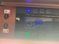
They are wired in parallel. Right now, with sunshine and no load, they will all be at 100% SOC
I know you've got a hybrid system...I'd have expected the LFP to do the donkey work for the first 3/4 of the discharge cycle and then the LA to catch up and finally take over, if so then the LFP will typically draw more charge current in a parallel setup because it's higher potential means it get's discharged sooner than the LA.
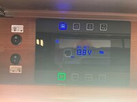
Indeed so. Most of the time, the system is basically running on a single 100Ah LFP. Only when being used when parked up for a long time (the solar panel is tiny) does the voltage drop to the point where the LA batteries do anything but sit at float voltage. Then after the voltage has come down, you can see the banks helping each other out. When the b2b is running, the LFP usually takes a lot more current than the LA until it is nicely full. When the engine is stopped, you can see rebalancing going on between the batteries. However, the hall effect sensors are not ideally placed at present, so they can be off by few hundred mA
Ultimately 200Ah of brand new lead acid would have an internal resistance similar to a 100Ah LFP battery and 200Ah of new lead acid would have been installed a gazillion times in the past in a gazillion motorhomes without a second thought about the low internal resistance burning out their alternator.
I don't think that the internal resistance is the relevant part here. Alternators expect to see the battery voltage to rise after quite a short period of charging.
I know that my motorhome originally had an 85A alternator. Allow 20A for the heater fan, 15A for the wipers, 15A for the fridge, 20A for the lights, 5A for the ECU etc: that leaves a whole 10A for battery charging. OK, I changed my alternator to a 215A one, but that's not what most people do.
 
Clearly we are talking about entirely different things. You are focussing on split charge cables and I am talking about cables connecting batteries to the 12v bus.

However, let's stick to your application (seems fair): if you have 20 metres of 2.5mm cable, that's 150 milliohms (assuming 19R per 1mm per kilometre: 7R6 for 2.5mm)
At 50A, you are looking at a voltage drop of 150/1000 *50 = 7.5v.
I can't see how that is acceptable - or have I done my sums wrong?
Sorry, I thought you understood I was intending to charge my LFPs directly from the alternator without a B2B.
The 20m was just an example but let's work with that figure.
I haven't checked your figures or maths but it looks about right and you know what you're doing for sure so let's take the 7.5 volts dropped at 50A as a given. You're correct, 7.5v is too much, because 2.5 mm cable can't carry 50A and is only good for about 12A so the current needs to be limited to that.
Assuming the alternator voltage is 14.4 volts and the lithium battery voltage is 12.9v (charging at 12A at 5% SOC) then the wiring needs to drop 1.5v.
At 12A, your maths suggest that 20M of 2.5mm cable would drop 1.8V so a bit too much and the cable length would therefore have to be reduced.
There's already some cable between alternator and starter battery along with a fuse (possibly 2), you'd really need to fit 2 more fuses in the positive charge cable and these along with the Durite contact resistance would limit current further, so the required cable length would be considerably shorter than 20m.... probably closer to 10?
 
I don't think that the internal resistance is the relevant part here.
Personally I don't think internal resistance is relevant in most cases where it's quoted as a significant influence by you tubers and people following suit and quoting the latest buzz term.
I've seen internal resistance responsible for burning out alternators, burning out cables, balancing batteries ( yes according to a you tuber it was variation in battery resistance over the charge and discharge cycle that was responsible for batteries in parallel equalising over time.
Fact is internal battery resistance is dwarfed by wiring resistance and that it's self is dwarfed by the effects of overpotential. LFPs Internal resistance is largely misunderstood and isn't massively different to lead acid.
 
Sorry, I thought you understood I was intending to charge my LFPs directly from the alternator without a B2B.
Yes, that is indeed what I thought you were planning. So the only limits on current are voltage and resistance.
The only figures you gave were 50A, 2.5mm and 20 metres, so those are the ones I went with. They seemed to make no sense to me. Clearly, you agree that they make no sense, and you hadn't intended to do what I thought you meant.
You do seem to be overlooking the existence of the starter battery.
Why not forget the whole SCR idea and parallel the batteries together? That's what I did for a few months after my second Sterling B2B failed, before I got round to buying a different brand (which is silent and has never given a moment's trouble).
 
Right I fitted the batteries today two 300amp eco-worthy lithiums. I think I done alright getting them in and wiring up
Now they came with a 25% charge. I have the van plugged in to the house on a 13 amp socket. It’s taking forever to charge these is this normal for the way I’m charging and just down to the large capacity of the batteries. Do I need to upgrade the battery charger or is this down to the supply from the mains being low.
IMG_0322.png
IMG_0321.png
IMG_0320.png
IMG_0319.png
 
Charging current seems low to me Wully if it's at 9Amps.

But I'm probably the last person to ask so wait until Merl or David come along! :)
 
Right I fitted the batteries today two 300amp eco-worthy lithiums. I think I done alright getting them in and wiring up
Now they came with a 25% charge. I have the van plugged in to the house on a 13 amp socket. It’s taking forever to charge these is this normal for the way I’m charging and just down to the large capacity of the batteries. Do I need to upgrade the battery charger or is this down to the supply from the mains being low.View attachment 150891View attachment 150892View attachment 150893View attachment 150894
It'll have nothing to do with the mains supply Wully.
What mains charger do you have? Looks like a 10A charger? Or maybe it's a more powerful charger and somehow it's been turned down? If it is and your 600Ah batteries came 25% charged then you've got to get 450Ah into the batteries at just 10A means you're looking at 45 hours to achieve that and a larger charger would be sensible.
 
Told you that electrical knowledge is limited, Merl - bright as a glow worm's armpit when it comes to this topic ... :ROFLMAO:. But I do understand syntax, which is more than the BBC sports journalists do - they report that Garnacho was fined for 'speeding to Liverpool Crown Court' which would require 2 prosecutions - one for speeding when leaving the Man Utd Training Ground, and a second for speeding to Liverpool Crown Court ... :ROFLMAO:

Steve

Akin to Jeremy Thorpe's Memoir about his career as an amateur boxer - 'My Hammerings in the Ring' :ROFLMAO:

Steve
Or when he and his mother opened a hotel on the south coast .
'Come to Seaview and be browned by the sun(?)'
 
Hi Merl here’s a photo of my vans charger. Looking at the electronic panel above my door it looks like there’s a sub menu for charging settings . I’ll take a photo of what they are at. I plugged it in yesterday at about 4pm it’s now at 97%

IMG_0324.jpeg
IMG_0325.png
IMG_0326.jpeg
 
Here’s some photos of control panel and what it’s set at these can be changed from board.
 

Attachments

  • IMG_0330.jpeg
    IMG_0330.jpeg
    714.1 KB · Views: 17
  • IMG_0329.jpeg
    IMG_0329.jpeg
    667.2 KB · Views: 17
  • IMG_0328.jpeg
    IMG_0328.jpeg
    643.9 KB · Views: 17
  • IMG_0327.jpeg
    IMG_0327.jpeg
    715.5 KB · Views: 17
Without a poke around and taking measurements with a DC clamp meter it's hard to say what's going on Wully.
The charger is supposed to deliver 22 Amps BUT according to the manual it goes into 'standby' mode after ten hours. Not sure what standby mode entails but it could equate to the 10 Amps that was being displayed on the images of the App?
You'll have to make a judgement as to whether your existing mains charger is up to your requirements and get it swapped out for a higher power model if need be.
Someone will be along soon to tell you that the charger is intended for lead acid batteries and you shouldn't be using it for lithium.... don't worry it'll be fine. Set the battery type switch to the upper setting (PB) and don't leave it running for days on end once the batteries are charged and you'll be fine.
1000014033.png
 
Why not forget the whole SCR idea and parallel the batteries together?
I feel I need to protect myself from discharging the starter battery accidentally due to a lot of habitation use. For minimum outlay and additional work the addition of a Durite would give me that protection. As a bonus it would also give me a very simple means of turning the alternator charge process off if needed simply by disconnecting the Durite low current ground wire.
 
Back
Top