Pudsey Bear
Full Member
- Posts
- 25,307
- Likes
- 42,890
I was impressed with my 4a + out of a 85w panel, quite old but a good make & covered in garage dust and crud, I may get upto 5a on a good day so poss 10a with two up there maybe.

You could use a 5-pin relay instead. connect the PV to pin 87a, the solar input to the renogy to pin 30, pin 85 to ground and pin 86 to either a D+ or an Ignition signal. Then you wouldn't have to remember to flick the switch over when driving, and then back again when stopped.I put a household 230vac 13A Fused DP switched fused spur in to isolate the solar, my solar will never exceed 13amps. I guess this may technically be wrong in some way!
But the only reason I 'had' to do this was the the Renogy B2B/solar 30amp has a quirk in that if it receives both a solar and B2B charge input then it limits each one to 15 amps. So when there is say 1Amp of solar and I'm driving my max charge is 15+1 amp total. When I turn of solar then B2B will supply 30A Charge. The one annoying thing about this Renogy B2B/Solar equipment.
")
This is my set up with IsolatorView attachment 140650 bottom right hand corner

for your PV Array size, you could easily just snip off a fair number of strands off the 6mm cable and put the remainder into the terminal of the switch you are fitting. Just make sure you don't leave any stands floating around exposed!Overkill I think for us, not keen on coiled mains cable, I'd shorten that.
2x85w on a good day can only give me approx 10a, so a double pole 20a switch should be fine, not pretty I grant you, and it may even arc but it will be brief (I think) and encased with nothing volatile nearby.
My biggest concern is getting these bloody great 6mm2 cables in, pliers will be needed to pre-bend them
That's a great ideaYou could use a 5-pin relay instead. connect the PV to pin 87a, the solar input to the renogy to pin 30, pin 85 to ground and pin 86 to either a D+ or an Ignition signal. Then you wouldn't have to remember to flick the switch over when driving, and then back again when stopped.
Using a 5-pin relay and 87a (NC) pin means that when the solar is active, the relay is not using any power.
And doing this would likely be cheaper than using a DP fused spur as well. Win-Win
 , I've a relay in my 'box of bits' if I can trigger it using a B2B active signal rather than trying to find the D+ even easier, Ill have a look
make sure it is the 5 pin 'changeover' relay. a standard 4 pin relay would not really be suitableThat's a great idea
did you read the post where he explained the situation?You seem to be implying that driving when the solar is connected, is a bad thing. I thought that panels have a built in diode preventing reverse current?
Personally if I want to fiddle with batteries I just undo the +ve wire from the solar regulator. I sometimes even remember to replace it afterwards, when I have traced the source of the dim lights by measuring the battery voltage as 10v.
NoHi
Can someone suggest whether or not I need a solar isolator between my 2x110 watt panels and my Victron MPPT regulator?
Thanks
Most if not all VSR (Voltage sensing relays)did you read the post where he explained the situation?
Beg your pardon, sorry obviously I didn't. As I have an old clonker with a moronic alternator that only puts volts out when it sees a demand, I haven't got entangled with intelligent alternators. . . . . . .
But I have just discovered a THING about solar panels, and intelligent isolators.
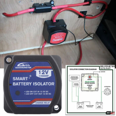
I bought an 'intelligent isolator' and fitted it. Not this exact one, but probably the only difference is the label on the front:
Split Charge Relay 12V 140A 140 AMP 0-727-33 Portable Power Voltage Sensitive | eBay UK
Note: The benefit of this type of relay is that it does not require a connection to the alternator or any modifications to the existing vehicle electrical system. Pressure Monitoring Systems. Car Care & Cleaning.www.ebay.co.uk
This is a reeeeeeeeeely clevvver device which would replace the changeover relay in a car/caravan combo or a motorhome without a solar panel. It sends engine volts to the LB when the alternator is producing its proper output. I have been fitting two Lifpo batteries and a Renogy inverter. I have an Epever regulator with two outputs, EB and LB. I finished hooking everything up and it all worked fine, the LBs were at 13.5v in the sunshine. The Epever was showing 13.6v output. Fair enough. However, I noticed that without the engine running, the inteligent isolator LED was on, indicating that the EB was connected to the hab wiring and therefore the LB as well. Thinking I had done some incorrect wiring I had a cup of tea and a biscuit and sat and looked at it for a while. Then I realised that the solar output was triggering the isolator because the panel was charging the EB, which was now at 13.5v and therefore triggering the isolator.
So the question is - do I rip out the intelligent isolator and replace it with the normal changeover relay, or just leave it connecting the two LBs to the EB, until their volts drop to 12.8v?
I think I know the answer. Another waste of £20, just like the other assorted glitzy things that look good on ebay / temu /amazon and so on. I've got plenty of 20A relays in the man shed. More wiring . . . .harrumph. I'll be soldering several of their pins in parallel. I don't trust these little plastic relays, having been brought up with GPO 2000 type relays with Platinum contacts. I'll need several relays - if the alternator can chuck out 95A then I don't want some poxy 10A relay contacts getting in between the alternator and two 100AH Lifpo batteries, not to mention that something in the hab area might be turned on . . .

It's just a quirk of using a VSR, because it closes at 13.3 volts it's bound to close whenever you charge the starter battery be that by alternator, maintenance mains charger or in your case solar. I don't think it's particularly bad BUT because the VSR is always monitoring the input voltage it will always be consuming a certain amount of standing current from the starter battery. Whether or not this will be detrimental will depend on the amount of solar you have and the standby current drain, if there's a large deficit it could cause a problem in the winter if the van's layed up.did you read the post where he explained the situation?
Beg your pardon, sorry obviously I didn't. As I have an old clonker with a moronic alternator that only puts volts out when it sees a demand, I haven't got entangled with intelligent alternators. . . . . . .
But I have just discovered a THING about solar panels, and intelligent isolators.
I bought an 'intelligent isolator' and fitted it. Not this exact one, but probably the only difference is the label on the front:
Split Charge Relay 12V 140A 140 AMP 0-727-33 Portable Power Voltage Sensitive | eBay UK
Note: The benefit of this type of relay is that it does not require a connection to the alternator or any modifications to the existing vehicle electrical system. Pressure Monitoring Systems. Car Care & Cleaning.www.ebay.co.uk
This is a reeeeeeeeeely clevvver device which would replace the changeover relay in a car/caravan combo or a motorhome without a solar panel. It sends engine volts to the LB when the alternator is producing its proper output. I have been fitting two Lifpo batteries and a Renogy inverter. I have an Epever regulator with two outputs, EB and LB. I finished hooking everything up and it all worked fine, the LBs were at 13.5v in the sunshine. The Epever was showing 13.6v output. Fair enough. However, I noticed that without the engine running, the inteligent isolator LED was on, indicating that the EB was connected to the hab wiring and therefore the LB as well. Thinking I had done some incorrect wiring I had a cup of tea and a biscuit and sat and looked at it for a while. Then I realised that the solar output was triggering the isolator because the panel was charging the EB, which was now at 13.5v and therefore triggering the isolator.
So the question is - do I rip out the intelligent isolator and replace it with the normal changeover relay, or just leave it connecting the two LBs to the EB, until their volts drop to 12.8v?
I think I know the answer. Another waste of £20, just like the other assorted glitzy things that look good on ebay / temu /amazon and so on. I've got plenty of 20A relays in the man shed. More wiring . . . .harrumph. I'll be soldering several of their pins in parallel. I don't trust these little plastic relays, having been brought up with GPO 2000 type relays with Platinum contacts. I'll need several relays - if the alternator can chuck out 95A then I don't want some poxy 10A relay contacts getting in between the alternator and two 100AH Lifpo batteries, not to mention that something in the hab area might be turned on . . .
I can't see it drawing anything significant ...I've ordered a couple of these.
Mainly because although there are what look like identical listings, this is the only listing that shows the insides, that look as if they might actually take the charging current. It's not going to be 100A of course but these look as if they have actual copper wiring inside and decent looking contacts, and I like the nuts and bolts wire terminations rather than push-on spades. I'll only use one for the battery charging and keep the other one in a drawer which my children will inherit and wonder what to do with. Unless I think of another use for one.
Until it arrives I'll look again at the installed VSR and see what current it draws when it is not turned on, but connected to the EB. It did get a bit warm when it was operational.
Those smartcom relays were frankly junk ...Not my best subject and I undestand a very small %age of these threads but I used the Smartcom VSR in the self build, a great bit of kit at the time.
Could you not use it the other way round as it is adjustable, to sense the solar energy input and the LB to send some charge to the VB?
Asking for a friend
Curtesy of Wissel
View attachment 140749