Hmm,
My knowledge of digital electronics is limited but FWIW here's my take.
In order to communicate the units will have to be connected to each other correctly AND speak the same language.
If you're connecting several
Victron devices together then their protocol (language) will already be the same so I'd expect them to simply connect together by a data cable, via usb (if possible?) then I'd expect that to simply plug and play but any other form of connection will require the correct orientation of the interconnecting wires, I'd also expect you'd need to connect between identical types of connector also so RJ45 to RJ45 etc, protocols likely differ across different types of connectors and this is where a raspberry pi will be used to convert the data. Conversion will probably be needed between different brands too.
RJ45s can carry both power and data over 4 pairs of cables, I'd expect the cable wiring to follow expected and standardised codes (pretty much exclusively pin 1 to pin 8, 2-7 etc) but of course they may not have. As we're talking standard TTL 5v logic levels here then getting the connections wrong should mean no harm will result to either device, just a lack of communication.
From 1cups post it sounds like the
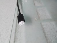
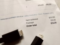
Victron data cables are super expensive? If so personally I'd buy just one bonafide
Victron data cable and test/deconstruct it to ascertain how it's wired and then clone my own to save money and keep the cables to the exact required lengths, I hate bunching up cables that are too long!


 I found working out circuits with Boolean Logic and the simple 74 series TTL chips very satisying and a lot more logical (
 . It didn't work! After checking and re checking my work I checked out the actual logic around the chips circuitry and reasoned that they'd made a mistake with the actual circuit diagram. A slight alteration to the wiring and I surprised myself and was as chuffed as a dog with two dicks because it now worked perfectly!