Something that has been on the radar from before I actually bought the to-be-converted Minibus was Heating!
In my last conversion I installed an Eberspacher D2 Airtronic Diesel Heater and it was great
")
but so it should have been as it cost over £600 (that is just the heater and parts, no installation costs as did this myself).
For Clarence, I wanted another Diesel Heater but with the cost of an Eber' D2 - which had risen to over £750 now for the kit only :scared: - I couldn't afford that so decided to risk the cheapo chinese Eberspacher clones at around £150. So a substantial saving on the cards there
.
The plan was to install under the drivers seat, same as I did on the VW T5 with the Eberspacher. I checked Youtube for any tips on installing on a VW LT (aka Sprinter T1N) as can always find a handy timesaver on 'the tubes' but not in this case

Lots of "installing an Espar D2 on my Sprinter" videos but all for the later Sprinters (the 2nd Gen NCV3 model) and while the seat base looks very similar, the under-chassis under the seat was
totally different. So on my own here (but as I tend to be old blue eyes ('I do it my way') anyway, suited me
")
So this is the space the Heater will be located in
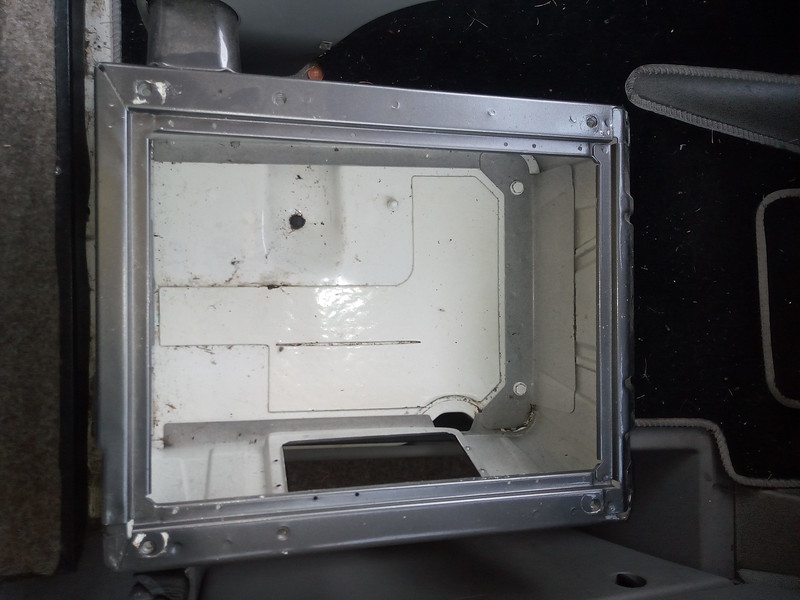
Empty Seat Base by
David, on Flickr
The electrics (fuses, relays, etc) are usually located under this seat but I had moved them to the other seat base a while back in readiness for fitting a heater here in the future.
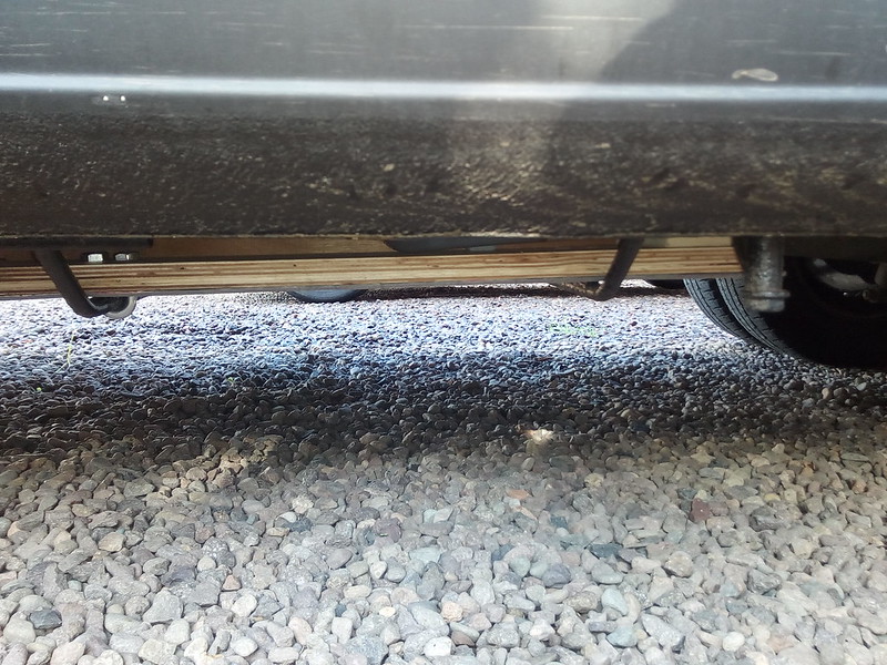
This is under the vehicle from around centre line towards outer side
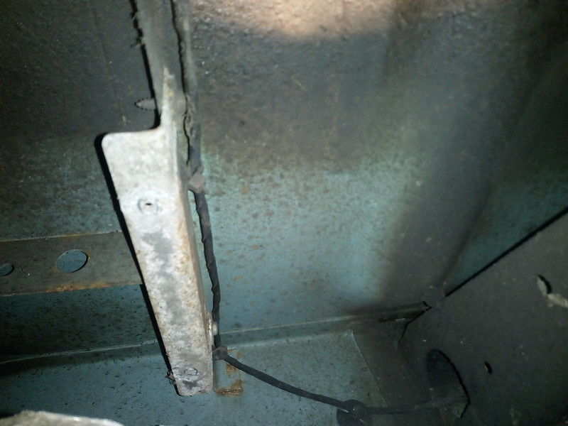 Underchassis under Seat
 by
David, on Flickr
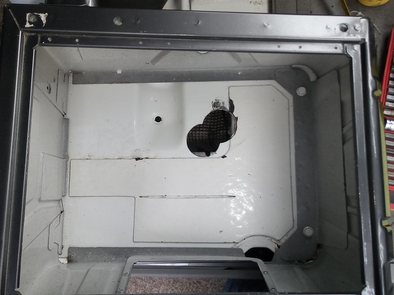
Looks fairly roomy but in fact not the case. The Bar with the cable clipped to it goes left to right and is around the upper third of the floor under the base. And the part at the end (where the cable curls round to carry on to) is actually a massive front to rear chassis support that is right in the middle of the seat base, so a major area inside the base is no use for the heater mounting.
Transferring the dimensions of obstructions from below to the base area, the options are very limited and this is what I decided on (rubber gasket shows the heater inlet/exhaust pipe positioning)
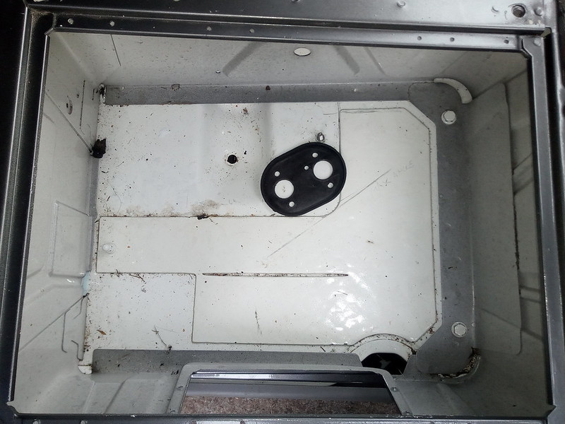
Best Location for Heater by
David, on Flickr
Essentially the white sheet just below the rubber gasket and to the right of the gasket are no-go areas for fitting. And to the left of the gasket there is a drop for cable routing which would make sealing a hole very tricky.
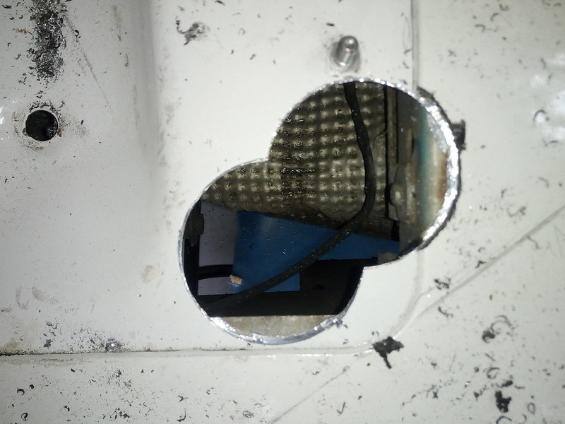
A couple of holes drilled out
Holes Drilled by
David, on Flickr
Close! by
David, on Flickr
You can see the exhaust shield below. This was dropped and moved out the way at the start (the photo showing the space underneath was actually taken with the camera in between the shield and the floor as the exhaust runs directly under where the heater is going!)
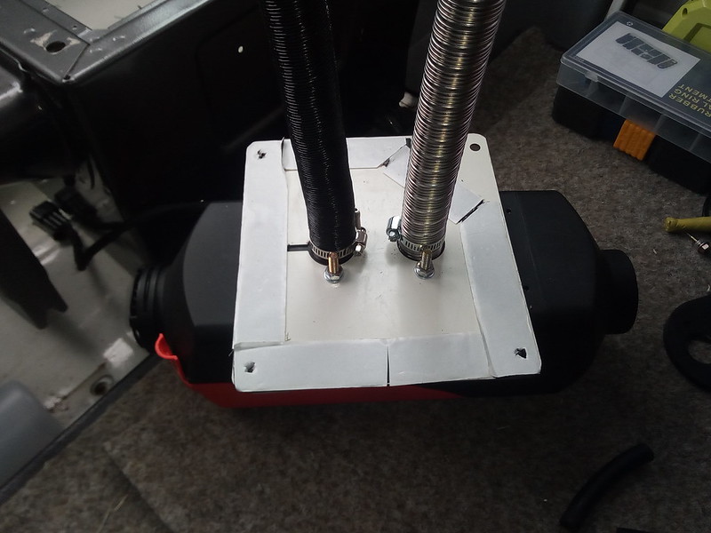
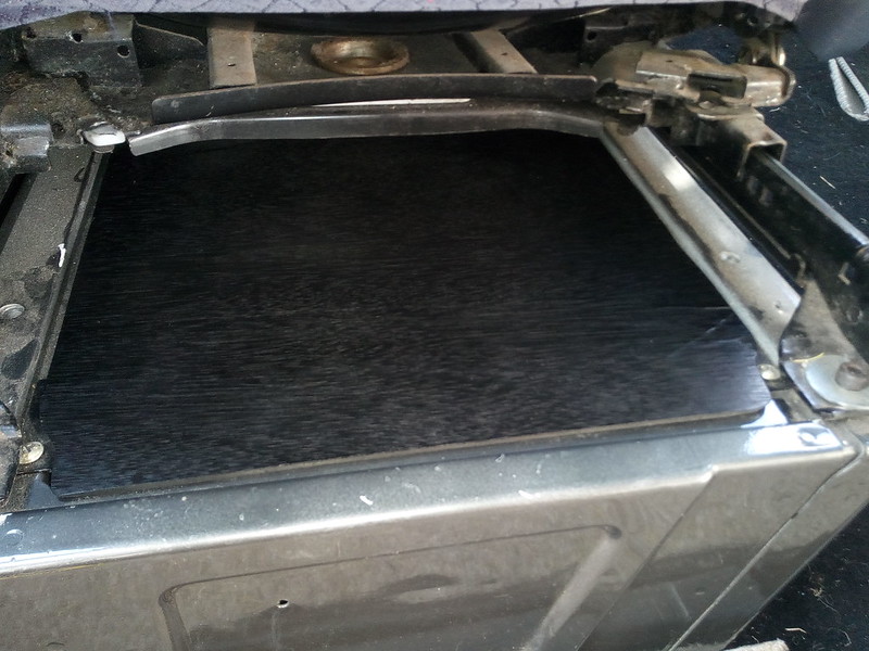
The Heater comes with a mounting plate
Mounting Plate with Butel Tape by
David, on Flickr
I specifically chose a kit with a plate (not all kits have them) as I think it is much better to make all the connections and secure them and then drop the lot in place as a oner rather then try and secure individual bits from underneath.
I added the tape as a sealing method. Much cleaner then using something like sikaflex in this situation.
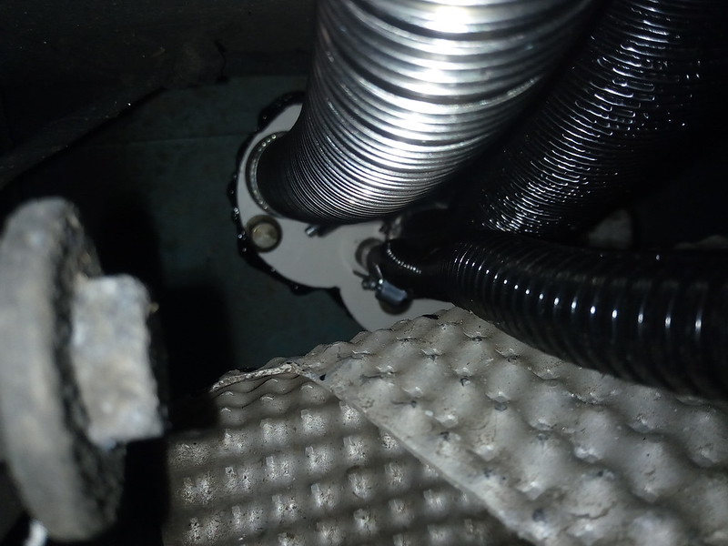
And dropped into position
Underchassis view by
David, on Flickr
(The black around the hole cutout is a heavy dosage of Hammerite to protect the cut metal)
Drilled out another hole for the heater outlet at the back of the seat base
Heater Outlet at back of Seat Base by
David, on Flickr
And a birds-eye view of the heater all installed
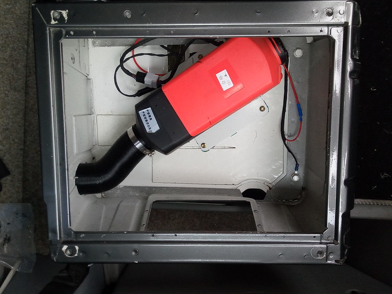
Heater setup and wired up by
David, on Flickr
I had previously run a 2.5mm cable in readiness for a heater so just routed this to the base and used a base bolt as the ground. (these heaters have a bit of a reputation for undersized cables leading to high voltage drops, so by chopping off most of the supplied power cable it will help eliminate that)
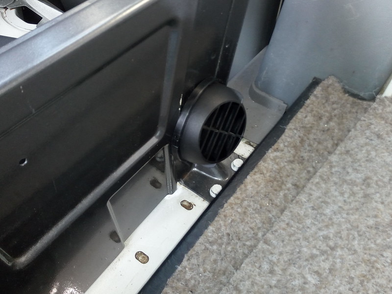
And the seat base cover refitted
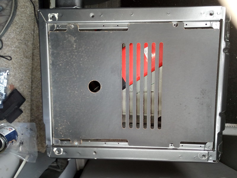
VW Hardboard Seatbase Cover by
David, on Flickr
I only have one of these (need one per seat really to protect the electrics under the other seat) and it has gone pretty droopy, so I made up a replacement in plywood
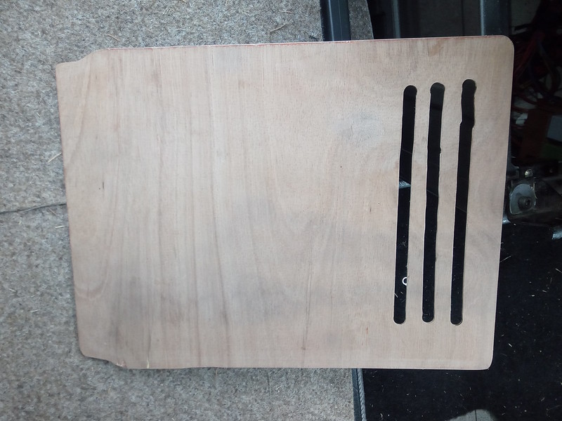
Replacement Ply Seat Base Cover by
David, on Flickr
I routed out some ventilation slots (unfortuatly the guide slipped on the first slot
), positioned in a place that would work better for the heater inlet and then sprayed black to blend in like the original
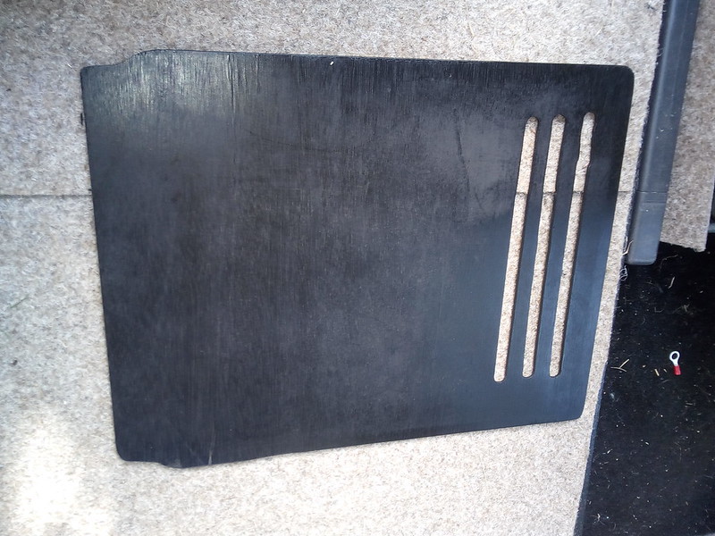
Ply Seat Base Cover Painted by
David, on Flickr
And put in place
Ply Seat Base Cover in Place by
David, on Flickr
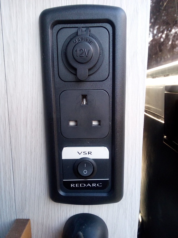
These Heaters come with a controller of course, but it is pot-luck to which one you actually get with the kit! My kit was shown with a fairly basic rotary controller, but I actually got an electronic LED unit
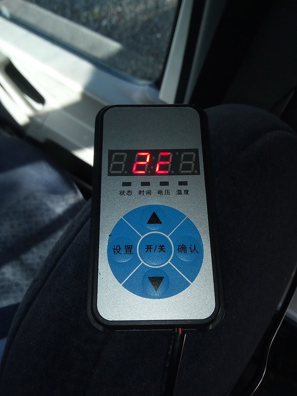
Heater Controller by
David, on Flickr
(due to the LED refresh, the digits don't show up properly in a photo)
Initial stumbling block as no instructions and buttons in Chinese, but now I have sussed it out, this controller is actually pretty good. It has a temp sensor in so you can set a target for the heater to go to; It also has a clock and you can set 2 timers for it to go and and off (it is just a 24 hour clock, no days, so you cannot set different profiles for say weekdays and weekends).
Overall ... nice unit. I have not yet worked out where to fit it (it has a holder it clips into so can be fixed to a wall say, and then unclipped and moved elsewhere. how useful that is I am not sure yet!)
OK, that concludes the Inside setup.
Now looking outside, I built a "Fuel Station" on a ply board (with protection underneath) which has a fuel tank, filter and pump all together.
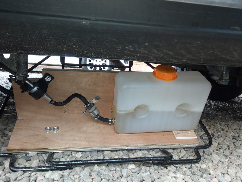
Fuel Station on Carrier by
David, on Flickr
I will be running the heater on Kerosene for a number of reasons;
1) These heaters have been reported to run significantly cleaner and better on Kerosene compared to Road Diesel
2) I don't have to drop the fuel tank to fit a standpipe (this would be made sigificantly harder on my specific van as well due to the way the step was installed)
3) Kerosene is a lot cheaper than Road Diesel (50p ish vs £1.30ish per litre)
I am fitting this to the redundant spare wheel carrier, so is very easy to drop for refuelling and maintenance, and otherwise is just raised into position and is virtually invisible
Fuel Station Raised by
David, on Flickr.
Moving to the Combustion area, you need Combustion Inlet and Exhaust.
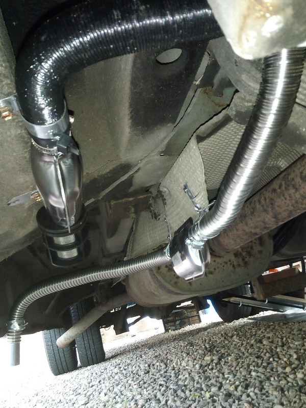
Inlet & Exhaust Pipes by
David, on Flickr
The Inlet Pipe is the black one, and the Exhaust is the silver one.
These had to routed to avoid the vehicle exhaust (as did the fuel pipe and power of course) but wasn't too bad a job to do.
The Inlet Pipe comes with an Air Filter, which is a nice feature and not something you get on an Eberspacher.
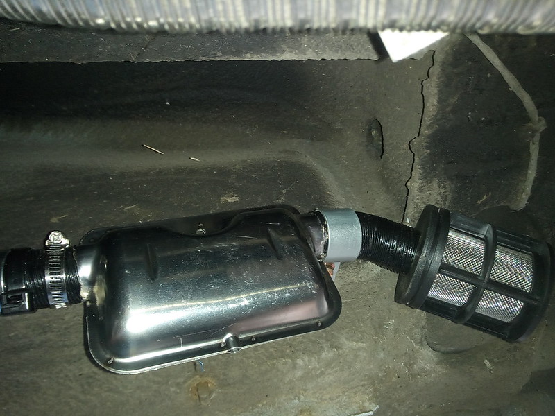
Inlet Muffler by
David, on Flickr
Neither do you get an Silencer by default (on either product). It may seem odd fitting a silencer on an inlet pipe but these are surprisingly effective. Check out this video I made showing the difference with and without (listen from around 15 seconds in)
[video=youtube_share;YcFty37nJ4M]https://youtu.be/YcFty37nJ4M?t=15s[/video]
This is the Exhaust Muffler, supported with some home-made P-Clips
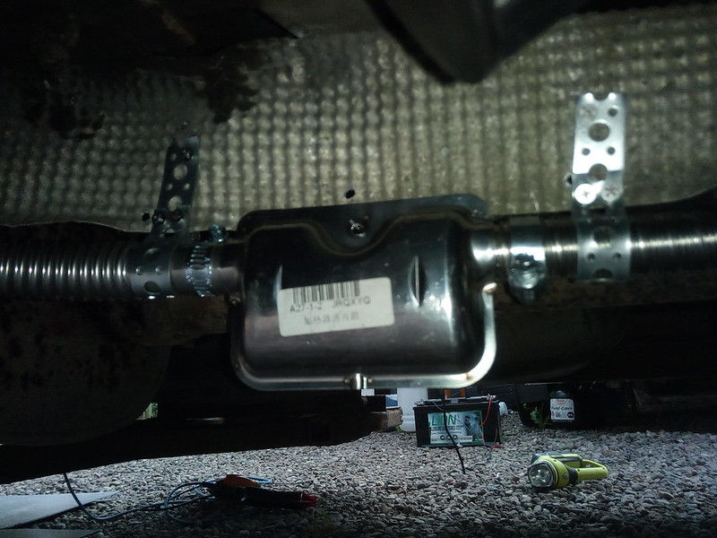
Exhaust Muffler by
David, on Flickr
Both of these Mufflers were bought separately in advance for this installation.
I have not checked the fuel useage yet, but in terms of Electrical Power, the heater draws around 11A in the first few minutes of use (mostly heating the Glow Pin I imagine) and then once running, draws just a few watts for the fan and pump.
Comparing this unit to the Eberspacher, it is to a degree 'you get what you pay for'. I installed another one of these heaters a couple of weeks ago into a VW T5 (not mine) and lessons learned from that install meant I bought replacement Jubilee Clips to repalce the poor quality ones supplied and some more rubber hose to use for joining pipework together. Also bought a length of Eberspacher exhaust as the supplied exhaust would not fit the silencers when cut.
I also tested this heater before installation and had to do some repairs as it would not run as delivered due to poor assembly. The casing is also very flexible which means the fan can easily rub (found this on both this heater and the one installed a fortnight ago). The Eberspacher casing from memory was much more solid.
So build and kit quality the Eber' wins, but have to bear in mind even after replacing and supplementing parts it is still a saving in excess of £500.
What these Heaters have over the Eberspacher is installation however! The Eberspacher install instructions are very cryptic; the wiring looms are all bare wires and the installer must fit the connectors and plugs. These Heaters are all pre-wired with plugs and electrically are totally plug and play. On the downside it might make cable routing harder, but a simple snip and resolder to route a cable if need be is fairly easy in the overall scheme of a heater install.
Early days yet, but I would buy another one of these heaters again - But I would also benchtest it before installing into a camper or motorhome.