
You are using an out of date browser. It may not display this or other websites correctly.
You should upgrade or use an alternative browser.
You should upgrade or use an alternative browser.
Clarence the Safari Camperbus
- Thread starter wildebus
- Start date
wildebus
Full Member
- Posts
- 12,247
- Likes
- 17,918
In my first setup, I used to have the big inverter switched on when using the Induction Hob and Water Heater; and the little 400W inverter always on driving the fridge and other bits and pieces like the Network kit and Amazon Echo.
Now I have a single 3000VA (2400W) Inverter, the overhead on small very low power AC devices is quite high, so made some tweaks ....

Amazon Echo Power by David, on Flickr
I fitted a pair of connectors to the lead rather than hard wired so if I move the Echo back inside I can plug in the original mains transformer again.
In terms of power use, the Echo uses 0.1A at 15V DC and the Router and Radio Booster uses 0.2A at 15V - so between them draw 4.5W when on, which is notably lower than the basic no-load overhead of a big inverter when on, so hence it seemed sensible to adapt the power source.
If I leave the router on 24/7 (which I tend to), the power use is around 6Ah a day. The Echo I tend to switch on when I want to use it, If I leave it on 24/7 when I am away in the van, it will pull 3Ah a day, so very little in effect.
This revised power setup also allows me to have the new Inverter in "AES" Mode, where it is basically off, but every few seconds comes on to check for a load. Doing this is a major power saver and reduces the Inverter overhead to a few Watts on average at times where there is no load.
As a Reminder, there is a regular load in the form of the Fridge - that is 35W for around 15 minutes every couple of hours; I have the Induction Hob and the Water Heater both used as required and the occasional other devices, such as Electric Blanket, Slow Cooker, etc. but only the Fridge is the predictable load.
Now I have a single 3000VA (2400W) Inverter, the overhead on small very low power AC devices is quite high, so made some tweaks ....
- Instead of using a Mains Charger for the hamster toothbrush, I got a USB version (fingers crossed as not yet tried it!)
- Got a little DC-DC step-up voltage regulator for the Network Router and instead of driving it with a Mains Transformer putting 24 DC out, I am just doing that directly
- Chopped the lead off the Amazon Echo power lead and using a Buck-Boost Regulator (so this will put out a set voltage regardless of the input voltage), set to 15V, I am running the Echo from the Leisure Battery as well.
Amazon Echo Power by David, on Flickr
I fitted a pair of connectors to the lead rather than hard wired so if I move the Echo back inside I can plug in the original mains transformer again.
In terms of power use, the Echo uses 0.1A at 15V DC and the Router and Radio Booster uses 0.2A at 15V - so between them draw 4.5W when on, which is notably lower than the basic no-load overhead of a big inverter when on, so hence it seemed sensible to adapt the power source.
If I leave the router on 24/7 (which I tend to), the power use is around 6Ah a day. The Echo I tend to switch on when I want to use it, If I leave it on 24/7 when I am away in the van, it will pull 3Ah a day, so very little in effect.
This revised power setup also allows me to have the new Inverter in "AES" Mode, where it is basically off, but every few seconds comes on to check for a load. Doing this is a major power saver and reduces the Inverter overhead to a few Watts on average at times where there is no load.
As a Reminder, there is a regular load in the form of the Fridge - that is 35W for around 15 minutes every couple of hours; I have the Induction Hob and the Water Heater both used as required and the occasional other devices, such as Electric Blanket, Slow Cooker, etc. but only the Fridge is the predictable load.
wildebus
Full Member
- Posts
- 12,247
- Likes
- 17,918
Opps :cheers:It still didn't stop you posting it twice though did it? :angel::lol-049:
I do enjoy reading these posts though
mariesnowgoose
Full Member
- Posts
- 24,261
- Likes
- 57,128
In my first setup, I used to have the big inverter switched on when using the Induction Hob and Water Heater; and the little 400W inverter always on driving the fridge and other bits and pieces like the Network kit and Amazon Echo.
Now I have a single 3000VA (2400W) Inverter, the overhead on small very low power AC devices is quite high, so made some tweaks ....
(Still waiting for the case to put the Regulator in)
- Instead of using a Mains Charger for the hamster toothbrush, I got a USB version (fingers crossed as not yet tried it!)
- Got a little DC-DC step-up voltage regulator for the Network Router and instead of driving it with a Mains Transformer putting 24 DC out, I am just doing that directly
- Chopped the lead off the Amazon Echo power lead and using a Buck-Boost Regulator (so this will put out a set voltage regardless of the input voltage), set to 15V, I am running the Echo from the Leisure Battery as well.
In amongst all the wonderful technical stuff you've posted, which I humbly confess not to understand at all, I was brought up short by the news that you have a pet hamster on board :rabbit:
")
Not only is that an unusual pet to travel with, I thought to myself, but the wee Ham has even been supplied with his own electric toothbrush!
What an extremely kind & thoughtful pet owner you are, David! Hat's off, sir... :bow:
")
wildebus
Full Member
- Posts
- 12,247
- Likes
- 17,918
it's really for my little hamster teeth in my own moosh
I am currently a bit underawed with the USB Charger. I tried it last night and put my nearly full (3 power lights on) toothbrush on it. Come the morning and I have one power light that is flashing (for low power). Looks like the charger base has sucked the power out
Put the brush on the 'proper' charger again and will check again but .....
wildebus
Full Member
- Posts
- 12,247
- Likes
- 17,918
Went to IKEA yesterday and bought a new drawer front Exciting huh!
Well, I use a 100mm high front where I blank off the sink to fit various devices and switches and needed to rework it after fitting the new Multiplus.
Looking like this now ...
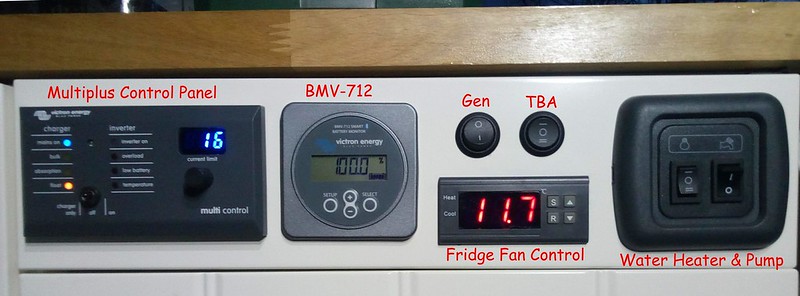
Control Panel (Labelled) by David, on Flickr (Labels for the photo not actually there )
So left to right we have:
Victron Multiplus Control Panel. This is a remote version of the Multiplus Panel with extra flexibility. It adds the ability to change the maximum input current on the fly with the dial control (so in the photo above it is set at 16 Amps). This will be very handy when stopping off at a site with a low power hookup (It won't actually really affect how the electric inside can be used as when the EHU current is reduced, the Multiplus goes into 'Power Assist' mode and makes up the difference using the Inverter. So just end up using a bit of Battery Power and then extra Battery Charging afterwards).
Victron BMV-712. Battery Montitor that also has a relay system that can control the Water Heater.
Fridge Fan Control. There is a Temperature Probe attached to the Fridge Compressor and goes to this Controller. Once a certain temp is registered, the controller switches on its relay to power a small 12V fan aimed at the rear of the fridge.
Water Heater and Water Pump Switch Group.
Water Heater - The left switch is a 3-way switch for the Water Heater. In position I, the Water Heater is controlled by the BMV-712 relay which gets enabled depending on the battery SOC Level; In position II, the Water Heater bypasses the '712; and in postion 0 the Water Heater is off.
Water Pump - The right switch simply connects or disconnects +12V to the Shurflo pump.
'TBA' Switch. Basically this is not connected to anything at the moment and just a spare
'GEN' Switch. This is a switch that is connected to the Multiplus Remote Control Panel. When the switch is on, the Current set by the dial control is overridden by a value that has been previously set. I programmed this to 7 Amps to suit my P2200 Generator which has a maximum running power of 1700W to ensure it will not go into Overload.
When the switch is on, the display changes to tell you it is in the Generator override mode
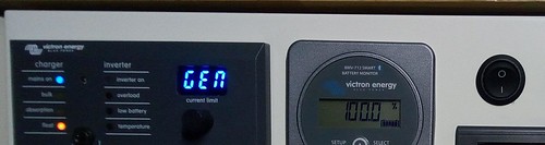
Control Panel (Gen) by David, on Flickr
Exciting huh! Well, I use a 100mm high front where I blank off the sink to fit various devices and switches and needed to rework it after fitting the new Multiplus.
Looking like this now ...
Control Panel (Labelled) by David, on Flickr (Labels for the photo
not actually there )So left to right we have:
Victron Multiplus Control Panel. This is a remote version of the Multiplus Panel with extra flexibility. It adds the ability to change the maximum input current on the fly with the dial control (so in the photo above it is set at 16 Amps). This will be very handy when stopping off at a site with a low power hookup (It won't actually really affect how the electric inside can be used as when the EHU current is reduced, the Multiplus goes into 'Power Assist' mode and makes up the difference using the Inverter. So just end up using a bit of Battery Power and then extra Battery Charging afterwards).
Victron BMV-712. Battery Montitor that also has a relay system that can control the Water Heater.
Fridge Fan Control. There is a Temperature Probe attached to the Fridge Compressor and goes to this Controller. Once a certain temp is registered, the controller switches on its relay to power a small 12V fan aimed at the rear of the fridge.
Water Heater and Water Pump Switch Group.
Water Heater - The left switch is a 3-way switch for the Water Heater. In position I, the Water Heater is controlled by the BMV-712 relay which gets enabled depending on the battery SOC Level; In position II, the Water Heater bypasses the '712; and in postion 0 the Water Heater is off.
Water Pump - The right switch simply connects or disconnects +12V to the Shurflo pump.
'TBA' Switch. Basically this is not connected to anything at the moment and just a spare
'GEN' Switch. This is a switch that is connected to the Multiplus Remote Control Panel. When the switch is on, the Current set by the dial control is overridden by a value that has been previously set. I programmed this to 7 Amps to suit my P2200 Generator which has a maximum running power of 1700W to ensure it will not go into Overload.
When the switch is on, the display changes to tell you it is in the Generator override mode
Control Panel (Gen) by David, on Flickr
Last edited:
wildebus
Full Member
- Posts
- 12,247
- Likes
- 17,918
I think it is integrated, not exchangable?Check the USB cable. It has to be fairly chunky to take the pulses without dropping volts. The ones that can fast-charge a phone are best. The ones that come with the charger are hopeless, in my experience.
Either way, I have done a return and bought another Mains charger base (I just wanted a spare base to keep in the van and thought a USB one would be handy as it seemed an option). Thanks for the info though. Something to bear in mind should I decide to try one in the future or for others looking.
wildebus
Full Member
- Posts
- 12,247
- Likes
- 17,918
For the last few weeks I have noticed my Battery Bank has gone to float charge a bit too early - Getting same result on both Mains Charger and B2B Charger, so something to do with the batteries, not the charger and a little strange 
Now back home after a week away wild camping and thought I would split the bank into the 4 separate batteries to check them. Still off-grid and engine not run for 2 days (but inverter still on to run fridge), turned everything off, removed the battery earths to isolate them all and checked a couple of hours later to allow the batteries to settle.
3 of the 4 were at 12.70V (so pretty healthy really), and the 4th Battery was at 12.90V.
So Battery Bank is looking pretty good but a little unbalanced - this could be confusing the chargers maybe. So currently put my Victron 20A charger onto its "Recondition" mode and recharging and equalizing each battery in turn until they move to "storage" status which I think will sort this out hopefully
It is the downside of multiple batteries in a parallel bank where even when they are cabled up to be perfectly balanced between each battery and all batteries bought and installed at the same time, individual Batteries will inevitably have some level of variance, so a periodic separation, check and rebalance is worth doing. (I did the same check around 4 months ago when the batteries hit a year old and had a maximum variance of 0.08V IIRC).
wildebus
Full Member
- Posts
- 12,247
- Likes
- 17,918
So to close the battery topic off:
Finished charging each one individually, complete with an Equalization charge;
Then put all the cabling back and did another equalization charge - this time with the Multiplus with the temp sensor fitted to get the right voltage level for the cold temp (hit 16V!)
Thought I would do a complete charge test now and also see what sort of charge I will be putting into the battery in the process. This will check the battery capacity and see how it matches the spec of the Battery Bank after 16 months of installation....
So with the battery bank fully recharged, left the van off-charge but with stuff running as usual to pull down the battery naturally - after about a week, down to 50% this morning at 10:00
 VRM RC - 7-3-19 - 50 by David, on Flickr
(PS. Low Power refers to the status of the Victron Multiplus, not the state of the Battery)
Charger pushing in maximum charge (~95A) for first hour, working in Bulk (aka Constant Current) Mode. Screenshot within that time shown below
 VRM RC - 7-3-19 - 54 by David, on Flickr
Charger switched to Absorption (aka Constant Voltage) Mode at 11:00 and current started to drop. Screenshot example below from 11:10
 VRM RC - 7-3-19 - 77 by David, on Flickr
In the Absorption Mode, while the voltage stays the same as the battery continues to charge (within temp variation), the current continues to drop at an ever decreasing rate, as is the way of a Lead Acid Battery. This is the battery after 2 Hours & 10 minutes of charging
 VRM RC - 7-3-19 - 87 by David, on Flickr
With the reducing charge rate it is not until 18:00 that the battery hits 100%
 VRM RC - 7-3-19 - 100 by David, on Flickr
Looking at the graph showing the SOC during charge, you can see the pattern illustrated in the screenshots above with the decreasing charge rate.
 VRM RC - SOC by David, on Flickr
Next step was to work out how many Ahs went into the Battery in the 6 hour charge time. This graph will tell us
 VRM RC - V and C by David, on Flickr
Calculated that the charger put in 216Ah into the system in the time, and the 50% of the nominal 380Ah Battery Bank means it was 190Ah Depleted. With just a few Ahs in that time used by the 12V electrics and the expected efficiency of the Multiplus it looks like a pretty good match of charge to replete the battery at the quoted capacity :dance:
And the key thing of course is that the charging pattern itself is back to normal and the equalizations sorted out the charge cycles :dog:
Finished charging each one individually, complete with an Equalization charge;
Then put all the cabling back and did another equalization charge - this time with the Multiplus with the temp sensor fitted to get the right voltage level for the cold temp (hit 16V!)
Thought I would do a complete charge test now and also see what sort of charge I will be putting into the battery in the process. This will check the battery capacity and see how it matches the spec of the Battery Bank after 16 months of installation....
So with the battery bank fully recharged, left the van off-charge but with stuff running as usual to pull down the battery naturally - after about a week, down to 50% this morning at 10:00
VRM RC - 7-3-19 - 50 by David, on Flickr(PS. Low Power refers to the status of the Victron Multiplus, not the state of the Battery)
Charger pushing in maximum charge (~95A) for first hour, working in Bulk (aka Constant Current) Mode. Screenshot within that time shown below
VRM RC - 7-3-19 - 54 by David, on FlickrCharger switched to Absorption (aka Constant Voltage) Mode at 11:00 and current started to drop. Screenshot example below from 11:10
VRM RC - 7-3-19 - 77 by David, on FlickrIn the Absorption Mode, while the voltage stays the same as the battery continues to charge (within temp variation), the current continues to drop at an ever decreasing rate, as is the way of a Lead Acid Battery. This is the battery after 2 Hours & 10 minutes of charging
VRM RC - 7-3-19 - 87 by David, on FlickrWith the reducing charge rate it is not until 18:00 that the battery hits 100%
VRM RC - 7-3-19 - 100 by David, on FlickrLooking at the graph showing the SOC during charge, you can see the pattern illustrated in the screenshots above with the decreasing charge rate.
VRM RC - SOC by David, on FlickrNext step was to work out how many Ahs went into the Battery in the 6 hour charge time. This graph will tell us
VRM RC - V and C by David, on FlickrCalculated that the charger put in 216Ah into the system in the time, and the 50% of the nominal 380Ah Battery Bank means it was 190Ah Depleted. With just a few Ahs in that time used by the 12V electrics and the expected efficiency of the Multiplus it looks like a pretty good match of charge to replete the battery at the quoted capacity :dance:
And the key thing of course is that the charging pattern itself is back to normal and the equalizations sorted out the charge cycles :dog:
Last edited:
Deleted member 69467
Guest
Blimey!
Nice build sir! Clarence.
Very well thought out and brilliant craftsmanship.
Great write up as well.
Nice build sir! Clarence.
Very well thought out and brilliant craftsmanship.
Great write up as well.