Victron solar controller.

Time to get a dvm out and do some point to point and local measurements, e.g. if you have used 4mm cables from the controller there shouldn’t be excessive volt drop at the relatively low current shown in your last screen I.e. 5A if all the connections are good.
His MPPT output was 19.5A on the screenshot he posted.

Screenshot_20230815_111102.jpg

He has 4mm cable running 4.5m. This gives a voltage drop of 0.82 volts. This means his 14.2v is only 13.4v by the time it reaches the battery.
 
Come on England 2-1
So I can set mppt at 15 volts ? Until I rewire .
NO!
As the current drops, the voltage drop will reduce, and you will over-voltage the batteries.

If I was doing it...

1) Move the solar controller as close to the batteries as possible.
2) If you have a 4mm PV cable already in place, then just join it where you have removed the solar controller. This will then extend the solar cables.
3) Use 16mm csa cables to connect the solar controller to the batteries (or busbar). This is to reduce the voltage drop, and your batteries will change faster.
 
His MPPT output was 19.5A on the screenshot he posted.

View attachment 122485
He has 4mm cable running 4.5m. This gives a voltage drop of 0.82 volts. This means his 14.2v is only 13.4v by the time it reaches the battery.
I was referring to his post number 9, if there’s still significant volt drop at 5A then he really does need to take some measurements especially if over the distance you mention because then with higher currents it can only get worse. It’s just the start of a fault finding process to rule out the basics.

Obviously common sense says move the controller closer and size the cabling accordingly but maybe that’s not an option.

The weird thing looking back at both sets of screen shots, the battery voltage is lower when less current is flowing from the controller which is exactly the opposite of what would one would expect, All things being equal etc, so the big unknown here is the load on the battery when the screen shots were taken.
 
Last edited:
It would be interesting to check both when the Orion is active and not active whilst you are checking (can see the amount of drop under load that way).

Next may or may not be applicable to the Orion, but is to the rest of the connected Victron kit ....
If you have a Venus OS device, such as a Cerbo GX or a Raspberry Pi running the Venus OS, you can enable some settings so all the physically connected devices have the same correct (actual) battery voltage, and also battery temp. Enable SVS (Shared Voltage Sense) and STS (Shared Temperature Sense) in the DVCC settings. That is a good idea to counter the inevitable voltage drops between chargers and batteries.
If you don't have a Venus OS system but your Victron kit is Bluetooth enabled, you can enable Smart Networking to do the same thing. I don't know if the Orion-Tr can be part of Smart Network or not (I might see if the one I have installed can be. As I run a Cerbo GX it is of not much interest to me directly). The Orion-Tr has still not been undated with a VE.Direct port which is quite disappointing so cannot play in a Venos OS system :(
I think I have smart network enabled, I'll try and check all of the above at some point 👍
 
Come on England 2-1
So I can set mppt at 15 volts ? Until I rewire .
That would be a mistake. You have spent all that money on expensive kit. Why don't you get the correct sized cables to go with it?

You don't need anything fancy. Any copper wire(s) will do.

If you only have 4mm cable, that'll do. You just need to run four, five or six of them side-by-side.

It'd be neater to use one decently-fat cable, but what matters is the cross-section of the copper.

Changing the voltage settings instead of using the correct cables is a good way to ruin your batteries.
 
This it 800w or 50 to 60amp on one hob is the pull but solar is connected to invertot as I still away and proper set up / install will be at Hereford with Jeff's 70mm wire and crimps. So it is temp setup till then. but must work . As we're been away since befor balloon festival last Thursday. Battery was collected on route to rye and stand alone until connected to mppt / SC at balloon festival.
I was referring to his post number 9, if there’s still significant volt drop at 5A then he really does need to take some measurements especially if over the distance you mention because then with higher currents it can only get worse. It’s just the start of a fault finding process to rule out the basics.

Obviously common sense says move the controller closer and size the cabling accordingly but maybe that’s not an option.

The weird thing looking back at both sets of screen shots, the battery voltage is lower when less current is flowing from the controller which is exactly the opposite of what would one would expect, All things being equal etc, so the big unknown here is the load on the
 
I pulled solar wire today ( swaped over) for it to charge 100ah battery as it was low 30% at 3pm now 100ah relion 930pm @ 76% and tomorrow will charge from SC mppt into jk at 55% tonight is switched back to 280ah 4 cell with jk bms.after 930 pm

1cup is solar controller connected back to jk 9pm ish after Sunset witch was lovely.
3 cup is smart shunt connected to relion now recharged.

Screenshot_20230816_230559_BMS.jpg
our bar back que is a glow on table

So Thursday could be our first 2 kwh yahoo's into 280 jk after cooked breakfast and coffee. .

20230816_203606.jpg
Screenshot_20230816_212532.jpg
 
Last edited:
Should I be running input long or output long to mppt ?.

Looking to get 4x 8mm nut bus bars at both ends of the 35mm red and black as its run 4,5m battery to mppt , and run b2b which is 16mm wire from both to bus bar to from same bus bar back to batteries, hoping that will be OK. will have cerbo at Hereford.and try to be able to Linked to all. Including invertor. Smart shunt. Making the 100ah relion battery dormant. But 100ah is still live till then. Charged from b2b.
Should I be running input long or output long to mppt ?.
As has already been said you should run long cables TO the solar controller (from the solar panels) and keep the cable lengths between the solar controller and battery as short as reasonably possible.
DONT alter the settings of the controller to try and compensate for the voltage drop on the cable, you risk damaging your batteries. Just move the solar controller as close to the batteries as you can.
The distance between the controller and the batteries will determine the cable size for the battery to controller cables, you can use the cable calc that Admin Phil posted and try and keep the voltage drop at the highest likely current below 0.05v (50mv) total.
The cable size between the panels and the controller wont affect the charge accuracy, it'll only affect the power loss. again use the calculator and punch in the details for the cables between panel and controller and look at the percentage loss this time. As you're running a 24V array this is immediately halved compared to 12v so you're probably not losing a massive amount and the fact that you lose more when you're harvesting more may mean that it's not worth the effort and cost, only you can make that choice.
 
Leaving aside the details of what kit you have installed and how big the cables are, I'm not clear about how you have sized your system.

Basically, you need to look at your power consumption and how it will be replenished.

If you charge using a b2b and you drive every day, you just need a day or two's power stored on the battery and an adequate b2b to provide that much power each day.

If you use solar, you need to decide what months of the year you'll use it, and allow for local insolation figures. They you have to hazard a guess about how long a spell.of bad weather you need to survive. I'd suggest a week or two.

Then you know how big your battery bank should be, how many solar panels you need and how thick the cable have to be.

You appear to be judging the performance of your charging system without allowing for how full the batteries are (or how full the controller thinks they are).

Perhaps I misunderstand what you are doing.
 
Should I be running input long or output long to mppt ?.
As has already been said you should run long cables TO the solar controller (from the solar panels) and keep the cable lengths between the solar controller and battery as short as reasonably possible.
DONT alter the settings of the controller to try and compensate for the voltage drop on the cable, you risk damaging your batteries. Just move the solar controller as close to the batteries as you can.
The distance between the controller and the batteries will determine the cable size for the battery to controller cables, you can use the cable calc that Admin Phil posted and try and keep the voltage drop at the highest likely current below 0.05v (50mv) total.
The cable size between the panels and the controller wont affect the charge accuracy, it'll only affect the power loss. again use the calculator and punch in the details for the cables between panel and controller and look at the percentage loss this time. As you're running a 24V array this is immediately halved compared to 12v so you're probably not losing a massive amount and the fact that you lose more when you're harvesting more may mean that it's not worth the effort and cost, only you can make that choice.
I've just done the maths for you and if you move the controller to within 1/2 a metre of the batteries then surprisingly you're losing less than 1% of the harvested power on the cabling between the panels and the controller.
Personally I wouldn't bother changing the cable, it's perfectly fine, just move the controller.
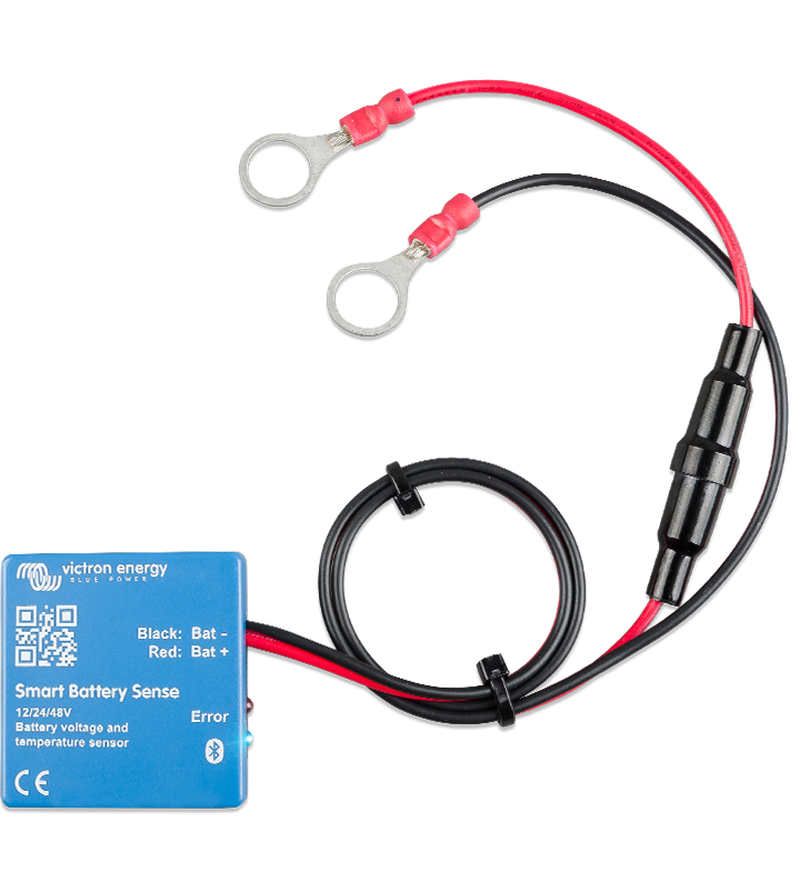
You could also consider using the Victron Battery sense which will compensate for cable losses and also adjust charge to suit battery temperature.

 
You could also consider using the Victron Battery sense which will compensate for cable losses and also adjust charge to suit battery temperature.

He has a Victron shunt which can provide precise battery data via Bluetooth to the MPPT. His battery is an LFP lithium with a built-in BMS that deals with cell temperature.
 
Why doesn't he simply use this option to ensure batteries charge at the correct voltage then Phil?
He can do that, but the MPPT won't output a higher voltage than the max it is set at to compensate for the voltage drop, so fixing the voltage drop should be his first priority.
 
But the smart battery sense linked to by clarkpeacock WOULD enable correct charge voltage yes? Victron blurb says:-
"By measuring voltage at the battery bank terminals, errors arising from voltage-loss due to cable resistance are avoided - guaranteeing the correct charge-voltage."
Just confused about the shunt doing the same job as the smart sense (re charge voltage control) which you seemed to suggest it did. Maybe I got the wrong idea or the smart sense doesn't live up to the blurb??
Confused!!:)
My thoughts as well. I have three systems with multiple charge controllers and large lead acid battery banks, each using a smart sense which seem to do just that. ( I live off grid so rely on solar completely for domestic power)

I installed these primarily for the temperature compensation feature on the recommendation of Rolls batteries.

Maybe I misunderstood the Victron description?

Here's one of my systems;
PXL_20220708_165047352.jpg
 
Last edited:

Users who viewed this discussion (Total:0)

Back
Top