another way of dimming LED's is this way....
Two popular methods for dimming LEDs in switched-mode driver circuits are Pulse-Width Modulation (
PWM) dimming and analog dimming. Both methods control the time-averaged current through the LED, but there are differences between the two. Simply put, analog dimming of LEDs is the adjustment of the constant LED current level. Analog dimming can be accomplished by an adjustment of the current sense resistor RSNS or by driving an analog voltage on a DIM function pin of the IC. A change in value of RSNS will correspond to a change in LED current with a fixed CS reference voltage.
An important disadvantage to analog dimming is that the color temperature of the emitted light can vary as a function of LED current. So for applications that require a constant color temperature, analog dimming is not suitable.
The
PWM method of dimming requires turning the LED current on and off for short periods of time. While
PWM reduces color changes in the LED with varying brightness levels found in the analog method, it is at the expense of additional circuitry. The frequency of this start-restart cycle must be faster than the human eye can detect to avoid a flickering effect. About 200 Hz or faster is usually acceptable.
With
PWM, dimming of the LED becomes proportional to the duty cycle of the dimming waveform, according to the formula:4
IDIM-LED = DDIM x ILED
Where IDIM-LED is the average LED current, DDIM is the duty cycle of the dim waveform, and ILED is the nominal LED current setup with the selection of RSNS.
PWM LED drivers often feature a specialized
PWM dimming pin that accepts a wide range of
PWM frequencies and amplitudes, allowing a simple interface to external control logic.
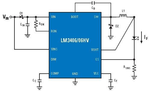
Two-wire
PWM dimming is a popular method for automotive interior lighting. As VIN is modulate below 70 percent of VIN-NOMINAL, the VINSM pin (Figure 2 showing the National LM3406) detects the change in voltage and converts the
PWM waveform into a corresponding
PWM of the output drive. The disadvantage to this method is the power source to the converter must contain a circuit to provide a
PWM waveform to its DC output.
Two-wire
PWM dimming
Figure 2: Two-wire
PWM dimming.
Dimming control parts
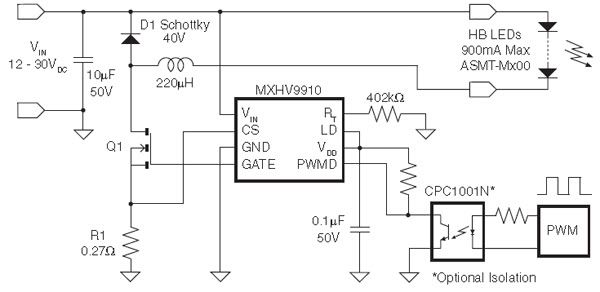
Other examples of LED dimming control include the MXHV9910BTR, a high-brightness (HB) LED driver manufactured using Clare’s high-voltage BCDMOS on SOI process. This driver has internal circuitry that allows it to operate from a universal AC line or from 8 to 450 VDC. LED dimming can be implemented by applying a small DC voltage to the LD pin or a low-frequency digital
PWM signal in the range of a few hundred hertz to the PWMD pin. The PWMD signal controls the LED brightness by gating the
PWM gate driver output pin gate. The signal can be generated by a microcontroller or a pulse generator with a duty cycle proportional to the amount of desired light output. When PWMD is low, gate drive is off; when PWMD is high, gate drive is enabled.
A linear dimming function can also be implemented on MXHV9910BTR (Figure 3) by applying a DC control voltage to the LD pin. By varying this voltage, the user can adjust the current level in the LEDs, which in turn will increase or decrease the light intensity. The control voltage to the LD pin can be generated from an external voltage divider network from VDD. This function is useful if the user requires a LED current at a particular level and there is no exact Rsense value available. A combination of linear and
PWM dimming techniques can be used to achieve a large dimming ratio.
Buck driver for
PWM dimming application circuit

")