
landrovereditor
Full Member
- Posts
- 29
- Likes
- 11
Looking through a lot of diagrams and threads on inverters, many just connect to the battery with no fuse or cut off switch.
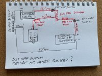
The diagram below is the one I propose to follow for wiring my inverter and fuse block to my battery.
The cut off switch is my stumbling block, do I put it between the inverter and the fuse or before the bus bar which obviously will cut off everything.
The inverter has an on off switch, the battery terminal is a quick release. Do I need the cut off? If so where to place it?

")
