I have the same problem on my Hymer S700 1992.
I was having problems with very dim habitation lights and the water heater began to fail intermittently (gas shut off because of low voltage). I suspected an earth problem, but on checking I was getting 8.5v on both sides of the fuses in the block, even with all the fuses removed even though the
battery was showing 14+v on hookup. I also had the amp meter going full deflection. I took the
fuse out for the (amp meter accessories)
fuse f6 and this brought the amp meter back to zero. I ran a separate wire fused at both ends direct from the
battery + to the point above the cooker where there was a spare spade terminal behind the panel. All my lights began to be bright again and there is now
battery voltage on one side of the fuses and 8.5v on the other. I assume this is coming from the
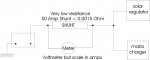
shunt which is shown on the wiring diagram as between fuses f6 and f7 which both go to the amp meter. I am now running without
fuse f6 in place and everything is working apart from the amp meter.
I thought the
shunt must be behind the panel where the big red switch is by the
fuse box to the left of the drivers seat. I have not been able to get behind there to look and was going to leave it to a professional when we return to the UK after the winter tour of Spain.
Can anyone can help both of us to locate the
shunt?
When I had a Waeco B2B fitted 2 years ago the amp meter would show discharge instead of charge, the professional who fitted it assured me that there would be no problem and that the leisure batteries were being charged OK. (Clip on amp meter proved this) I have had other problems associated with this B2B and now doubt the professions opinion.