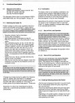
 View attachment 9874
Attached this time is a jpg version of page 12 of the workshop manual (you may need to "ctrl and +" to read clearly)
Tony, your post was a breakthrough. Page 12 now makes more sense although the order in which those two contact sets changeover is still not clear (to me!)
This thread is concerned with the type of installation in 1990's Lazer/UVG ambulances now converted - or in the case of Daisymini, being converted to MH. It's a basic installation, controlled only by a one stage (simple changeover contacts only) and a switch on the dashboard.
There are a lot of variations in the way Webasto heaters work, not least the type of electronic control unit used. In this case it's a SG 1561 GS, easily identified as the only one that has a 14 pin plug.
The diagram in my OP seems to show S8's contacts in what the text describes as "open". and which must mean "on demand" (air temp lower than stat setting)
On closing S9, 12v goes via upper contact to plug A pin 6. (but not pin 3). heater starts on full power as per text 5.1.1 including the NOTE which is relevant.
Full power can be interrupted - and heating stopped - by removal of the 12v on A6 (first para of 5.1.2) 0 volts on A6 and A3
Now it gets less clear :-( 5.1.2.1 describes what happens next. ie. Thermostat (B3) closes with no clue as to which contact set is involved. But 12v sent to Pin3. This is the low heat situation. At this stage closure of either contacst can cause 12v to pin3 and still leave 12v on Pin6 (but does prove Tony's "Power on both Pin 6 and Pin 3 -->> LOW fire")
Leaving aside the sequence of the S8 contacts This page of info seems to be telling me that with a two stage thermostat the heating system may alternate between HIGH and LOW power and to OFF if the temp rises sufficiently. (OFF is when both contacts close)
So what are the options if the system was wired with a simple one stage thermostat - possibilities:
1) heating switch is ON, on FALL of temp thermostat feeds 12v to pin 6 only. System cycles between HIGH and OFF and no use is made of the LOW power mode.
2) heating switch sends 12v to pin 6 and thermostat sends 12v to pin 3 on RISE of temperature. system cycles between HIGH and LOW. (but not OFF)
My own van had a relay an a timer associated with the (one stage) thermostat wires but I've no idea what they did. As option 2) could never turn itself OFF completely whatever the temp rose to I wonder it was used to set a maximum time it could run for.
Remember these are thoughts not facts..open to more comment or observation..but there is progress !
Tony..I think the logic of the two C/O contacts in B3 is such that pin 3 can never be at 12v by itself so I think that "
Power on Pin 3 only -->> No fire" is not right.


