Autotrail EMC Relay Question

GeoffL

Full Member
Posts
2,433
Likes
7,734
I have electrical issues with my 2001 Autotrail Scout (Ducato based) that I suspect might be due to a duff EMC relay. AFAICT most UK motorhomes of this era were fitted with an "EMC Relay", which is a lateral thinking method of getting around the EU EMC regulations for all the habitation electrical kit in the motorhome. Basically, it seems that this relay is designed to shut down habitation 12v electrics when the engine is running to allow the manufacturers to treat the caravan side of a motorhome like a trailer caravan!

The symptoms in my case are:
  1. The habitation 12v doesn't shut down when the engine is running (although this did happen when I first bought the van until one day I turned on the 12v switch when the engine was running).
  2. The grey water tank full alarm sounds when driving (which the handbook says shouldn't happen).
  3. There's a large voltage drop in the 12v habitation system when drawing only a few amps even though voltage at the battery terminals remains unchanged. For example, turning on 8A worth of lights drops the system voltage to around 10v, at which time the battery terminal voltage might be 12.4v.

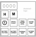
I've attached a diagram of the control panel layout to help identify which version of 12v system I have. Can anyone tell me where this relay is fitted and whether I can fit a manual alternative so that I can run the engine to provide habitation electrics for short-term emergencies?

Thanks for looking, Geoff
 

Attachments

  • Control Panel 2.jpg
    Control Panel 2.jpg
    71.4 KB · Views: 144
Normally the dealer who sells the motorhome from new will have disabled this relay, but maybe some owners don't dare change anything from maker's design (might reduce resale value).
But it sounds like your won't have had that fix.
Your description suggests another problem, and I think it needs to be looked at by a competent auto electrician.

Thanks. FWIW, I have an electrician friend (who's worked on everything from 12v dc to 440v 3-phase in a marine environment) who's offered to help. I'm also a lapsed radio amateur, so between the two of us we should have enough expertise to do whatever a competent auto electrician would be able to do. I'm just trying to get a handle on things before we start ripping out the panel and possibly dismantling parts of the internal habitation structure. The reason I suspect that I've got a duff EMC relay is because the electrics initially cut out when I started the engine but this changed after I switched the 12v back on when the engine was idling. As the job of the EMC relay is to disconnect habitation electrics when the engine is running, it seems likely that I have a duff one.

Whatever, experimentation shows that there is a voltage drop between the battery and the voltmeter in the control panel that increases linearly with increased current, which means there is resistance somewhere in that leg that I need to find. That resistance is only about a quarter ohm (2v / 8A), but gives rise to a significant voltage drop when the system is under all but the lightest load.

So the plan is to carefully unmount the panel from the wall to get access to the terminal strips at the back of the panel. Hopefully, I'll find the EMC relay mounted externally to the panel (but that's by no means a given) and (also hopefully) it'll be relatively easy to check the voltage in and out of that relay with the system under an 8A load. That should tell me whether the relay is at fault, whether the wiring feeding the relay is at fault, or that the fault lies between the relay and the panel voltmeter. A similar check should tell me whether the wiring between the relay and the panel is at fault or whether the fault is internal to the panel. I have a horrible feeling that a new 'original' panel will be horrendously expensive, so I hope that any faults lie before the panel itself.

AFAICT (but I'll rely on my friend's expertise here), if the relay is the problem, I have the following options:
  • Fit a new, functionally equivalent relay. This will turn off the habitation electrics when the engine is running and get rid of the annoying sounding of the high grey tank alarm every time I move the van with a few litres of waste water in the tank, but it won't allow me to use the habitation electrics with the engine running.
  • Fit a new, functionally equivalent relay and fit a switch in the positive primary wire to that relay. This will achieve the same as the previous option but allow me to disable the EMC relay for rare occasions when I need to use habitation electrics with the engine running.
  • Replace the relay with a switch and isolate or join the primary wires as appropriate dependent on whether the primary circuit has other equipment in series. This will let me have the habitation electrics permanently available while giving me the option of turning them off to silence the high grey alarm.
Of course, I could alternatively fit a switch in the high grey tank sensor feed to the panel, which would allow me to just disable the alarm.

That said, before either my friend and I (or a competent auto electrician) can do any of this work, we need to know where Autotrail or their contractor have stashed this relay...
 
Whatever, experimentation shows that there is a voltage drop between the battery and the voltmeter in the control panel that increases linearly with increased current, .

Just to confirm understanding. If there is a known resistance, then terminal or final voltage will drop as current increases ?
 
Just to confirm understanding. If there is a known resistance, then terminal or final voltage will drop as current increases ?

Yes, that's correct. Don't forget that it's the voltage drop we're considering here, not the absolute voltage. It's the voltage drop that increases as the current increases. In my case, the voltage drop between the battery positive terminal and the panel voltmeter is zero at no load and increases linearly with current to 2V at 8A. So (assuming the voltage at the battery positive terminal remains at 12V) the habitation system gets 12V when there is no load, 11V (i.e. 12-1) when the system draws 4A, and 10V (i.e. 12-2) when the system draws 8A.

The relationship is usually known as Ohm's Law and given the equation "V = RI" where V is the potential difference, R the resistance and I the current. Dividing both sides by "I" gives [sup]V[/sup]/[sub]I[/sub] = R. That is, the ratio of potential difference (i.e. 'voltage') to current is a constant, which is a linear (straight line) relationship. If V is in Volts and I in Amps then R will be in Ohms.

In that case it might the quality of the installation, the thickness of the cables, the specification of the connectors.

Would it be worth bypassing it all and try a fresh install.
 
In that case it might the quality of the installation, the thickness of the cables, the specification of the connectors.

Would it be worth bypassing it all and try a fresh install.

It might well be the installation between the battery bank and the panel. That's why I need to check the voltage in and out of the relay while the system is under load. I know that the voltage at the point of measurement within the panel and so know that the problem lies somewhere between the batteris and this point. A large voltage drop between the batteries and the relay input suggests that the supply cabling has issues. A large voltage drop across the relay suggests that the problem lies in the relay. Negligible voltage drop between the batteries and the relay output suggests that either the cabling between the relay and the panel or the panel itself has issues. I need to take some measurements to pinpoint the location of the problem and can proceed from there.
 
I suggest you ask Autotrail ...

I have sought advice from them a couple of times and they have been helpful and quick to respond.

Their website has a contact form which is the way I made contact.
 
To dot the "i's" and cross the "t's", my friend and I decended on the van yesterday to see what we could see. We found that the EMC relay was mounted inside the wardrobe/drawer unit on the wallboard just above the control panel. However, it was working as designed. We contacted Autotrail for information, and they were very helpful. Tracing the wiring and also the circuit diagram showed us that the EMC relay was fitted to the panel output (rather than the input as expected) and turned off some, but not all, of the habitation electrics when the engine is running. Rather strangely, the high grey waste sensor is not one of the items affected by the EMC relay.

We found the voltage drop in the supply line. It looks like the original wiring doubled up on the cabling that runs almost the entire length of the vehicle between the leisure battery and a junction at the front of the vehicle into which the split-charge relay feeds, and from there to the panel. The second cables (both positive and negative) were disconnected (possibly because of a broken connector block) and hadn't been made properly safe (we noticed some sparking when we moved the gaffa-taped mass and, when we removed the tape, noted that the wires had come out of the connector block).

So, the plan to resolve the voltage drop is double-pronged:
  1. Reinstate the doubled-up wiring, which should resolve any issues with charging from the alternator;
  2. Fit a fused bypass cable from the 12v distribution post to the panel 12v input, which will reduce the wiring length between battery and panel to about 1.5m and so should reduce the voltage drop to the habitation electrics as much as practicable.
I'll also fit a switch in the grey waste level sensor line so that I can disable the alarm when necessary.

Thanks to all who helped, Geoff
 

Users who viewed this discussion (Total:0)

Back
Top