Battery monitor

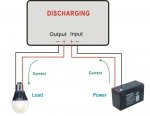
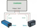
I doubt it, but I don't know the Sargent EC480, I have had a quick look on ebay and no wiring diagrams for the ones there, no thick connectors, you might be able to link it in to tell you what the draw is when you switch items on. Have a look at the following link, the various pictures, it show in effect how it would be fitted in-line without a shunt for the basic 30amp unit. I think it the same meter as the other link, less info and slight difference in price. It shows a charger but that could also be your alternator. Battery Tester DC LED 90V30A Digital Voltmeter Ammeter Voltage Gauge Panel Meter 754610748905 | eBay
Hello Charlie The image shows just 4 light weight connections + - In & Out. If not connected to existing Sargent wiring, which feeds should be used.
https://i.ebayimg.com/images/g/AvUAAOSwgY9XcpiB/s-l400.jpg
Many thanks to yourself or others that have the answer. Graham
 
Hello Charlie The image shows just 4 light weight connections + - In & Out. If not connected to existing Sargent wiring, which feeds should be used.
https://i.ebayimg.com/images/g/AvUAAOSwgY9XcpiB/s-l400.jpg
Many thanks to yourself or others that have the answer. Graham

s-l1600LER60SG2.jpg

s-l1600737TSAEX.jpg

Yes it shows 4 connections, light or medium, it appears the makers use that system for 10/20/30 amp meter, this is what they feel is suitable up to 30 amps, above that they use a separate shunt in the system, that way lighter cable can be run to the monitor and the monitor can be fitted further away from the connection point, that's with a separate shunt, the price goes up but allows a meter with a higher amperage to be used. I assume you are using this on your leisure battery ? If I was fitting this I would probably connect it in near the leisure battery on the + & -, I might even mount it near the leisure battery as it's under the passenger seat, at least as a test, you don't want to run the cables to far with the 30 amp unit. As I said I don't know your set up. I also don't know this meter, it was mentioned by someone else initially, but it turned out that they had a larger meter with a shunt.

You may find that this 30amp unit is to small for your system, that will depend on your vehicle, size of alternator fitted, size and type of batteries fitted, AGM batteries can accept a higher charge amperage than gel batteries. My gel battery take approx 25amps when low but soon cut back to 10 amps, so I would get away with using the 30amp meter, I would be more likely to buy a higher amperage version with a shunt as the 30amp version wouldn't work for me if I doubled up on my batteries or changed to AGM.

I have one of these Sealey SPECIAL Clip-On Ammeter 0-30 Amp any direction 5024209003018 | eBay Handy as a quick test, not that accurate but there are other clamp type meters on ebay.
 
You mention drain from the radio a lot - just how much power is your radio using when it is off? it should be so small to not care UNLESS it has been wired up incorrectly.
The drain across the permanent feed fuse in the fuse box is 195ma, it turns out that 10ma is what is supposed to be the memory feed and 185ma, (unit switched off), is a drain on what should be the ignition feed through the radio. As there is no auxiliary key position or override on the radio, (like some more modern systems), the standard procedure was to cut the ignition feed into the radio and join the feed into the radio to the permanent memory feed; That way allowing the radio to be used when parked up. Never a very satisfactory way of wiring a radio in, ok with none memory push button radio systems or if the set didn't draw power when turned off, apart from minor memory (10ma) as you correctly stated. Unfortunately mine does draw this 185ma.

Incidentally it also turned out that the feeds in the Fiat wiring loom were reversed according to the German Radio Manufacture's ISO wiring layout, they point this out in their manual that some Manufacture's reverse the wire the radio plugs.

So looking at the issue again:idea-007: I will fit a delay timer relay with a trigger switch, the radio is now wired up to ignition only. When set up with timer in standby mode the timer draws 20ma, in working mode its 50ma, the timer I have ordered is adjustable but will be set for about 4hrs. After that time it will drop back to the 20ma and cut the radio out. Working it through the battery monitor system would have drawn more power, the 185ma down to the set voltage, hours and hours, then 50ma to operate the cut off relay and monitor power till the battery was flat. So on the radio side in stand by mode, I will in effect go from 195ma down to 30ma, that will make me:)

I had no intention of cutting everything off, I was just making the point that there are many other types of drains upon the batteries. At the moment I can't check it at the battery as the front of MH is against a wall and the back just fits in the drive, I will do that another time to see what the other items are drawing, I hope not to much.
:have fun:
 
suspect you're looking for something a little fancier than this,....I find it very handy.
I keep mine pugged in all the time....interesting to watch the voltage changes under various conditions.
hard to beat at £4.

Digital 12V/24V LED Car Cigarette Socket Voltmeter: Amazon.co.uk: Electronics

should check against a known acurate volt meter.... mine reads 0.2V under the true voltage.

and mine didn't read 12.5 volts at all when tested with a bench supply and Fluke meter, cheap and cheerful.
 
The drain across the permanent feed fuse in the fuse box is 195ma, it turns out that 10ma is what is supposed to be the memory feed and 185ma, (unit switched off), is a drain on what should be the ignition feed through the radio. As there is no auxiliary key position or override on the radio, (like some more modern systems), the standard procedure was to cut the ignition feed into the radio and join the feed into the radio to the permanent memory feed; That way allowing the radio to be used when parked up. Never a very satisfactory way of wiring a radio in, ok with none memory push button radio systems or if the set didn't draw power when turned off, apart from minor memory (10ma) as you correctly stated. Unfortunately mine does draw this 185ma.

Incidentally it also turned out that the feeds in the Fiat wiring loom were reversed according to the German Radio Manufacture's ISO wiring layout, they point this out in their manual that some Manufacture's reverse the wire the radio plugs.

So looking at the issue again:idea-007: I will fit a delay timer relay with a trigger switch, the radio is now wired up to ignition only. When set up with timer in standby mode the timer draws 20ma, in working mode its 50ma, the timer I have ordered is adjustable but will be set for about 4hrs. After that time it will drop back to the 20ma and cut the radio out. Working it through the battery monitor system would have drawn more power, the 185ma down to the set voltage, hours and hours, then 50ma to operate the cut off relay and monitor power till the battery was flat. So on the radio side in stand by mode, I will in effect go from 195ma down to 30ma, that will make me:)

I had no intention of cutting everything off, I was just making the point that there are many other types of drains upon the batteries. At the moment I can't check it at the battery as the front of MH is against a wall and the back just fits in the drive, I will do that another time to see what the other items are drawing, I hope not to much.
:have fun:

ref the Radio, I had a feeling that the signal/ignition +12V into the radio was wired to the permenant +12V. And with newer radios, the "Off" button on the radio does not actually turn the radio fully off in most cases, so there is a much larger drain then there should be.
This is a common issue with aftermarket radio installations on newer vehicles. See this a lot in the VW Transporter world where the standard radio is a Canbus connected unit via the new-style Quadlock connector found on newer vehicle, and the Quadlock connector has no ignition feed signal, so often DIY (and 'professional' for that matter) just connect the radios ignition +12V to the permanent +12V as it is easy to do.

I actually have a wiring kit especially for VWs (and other VAG vehicles) that deal with this, and also what I call a "Drive/Camping Radio Loom" kit which allows you to use a 3-way switch to feed the radio ignition with the Ignition signal (the "Drive" mode), or from a permanent +12V signal (the "Camping" mode), or just off (handy if you want to turn your ignition on late at night/early morning on a campsite and don't want to blast the neighbours).

Interesting comment about the Fiats wiring being reversed according to the Germans :) I think it is more likely that the German Standard is the one the wrong way round ;) As when installing any aftermaket radios , if you are installing into a German vehicle with ISO plugs you have to swap over the red (ignition +12V) and yellow (perm +12V) wires, but on any others it is still red-red and yellow-yellow (these are the radio industry standard colours)

I will check the drain on the car as that has one of the, what I am calling the ignition/auxiliary override button on the radio, that is over ridden by the ignition switch again so automatically goes back to normal operation, a much better system, original fit in my Peugeot and the Co-Pilots Citroen.

I think my unit has a much higher current draw on the ignition feed circuit even when switched off than most, but I can't really remember now what the norm was. When I was fitting radios some 25+ years ago most of them were just standard push button radio cassettes, I did a lot of work on trucks, when I did fit the type of unit that I have in the same situation, (as a professional), I hoped it had an auxiliary feed. Most vehicles get driven every day so not a real issue. It has to be my MH that has to be wired into the permanent, been meaning to sort it out for ages. I could have fitted a switch in the system but I would have probably left that in the on position and still flattened the battery, as I said I hopefully remembered to pull the fuse out when parked up at home.. So I think the timer relay is a good way for me to go, and its adjustable from a few second up to several hours.

I was surprised to hear you say that you thought it was the Germans who got the wiring wrong,:raofl: I used to know the head of a UK Technical Dept of a well known German Auto Electrical Manufacture, and he had the opinion that it was all the other countries, (well England as that was where he was based), that were well behind the Germans and implied we didn't know what we were doing.:mad1:
 
How to connect display monitor?

Hello all
I've just purchased and thought it would be simple to wire. However I need some help with the wiring. It seems that the monitor can be wired to show either the charging state or the usage but not both,is that so?
Looking forward to hearing from you soon. Many thanks Graham
 
How to connect display monitor?

Hello all
I've just purchased and thought it would be simple to wire. However I need some help with the wiring. It seems that the monitor can be wired to show either the charging state or the usage but not both,is that so?
Looking forward to hearing from youhttps://www.wildcamping.co.uk/forums/redirect-to/?redirect=https%3A%2F%2Fwww.ebay.co.uk%2Fitm%2FBattery-Tester-DC-LED-90V30A-Digital-Voltmeter-Ammeter-Voltage-Gauge-Panel-Meter%2F142142090671%3F_trkparms%3Daid%253D111001%2526algo%253DREC.SEED%2526ao%253D1%2526asc%253D20131017132637%2526meid%253Dfebba087561e48258d30dc5fa75593f5%2526pid%253D100033%2526rk%253D2%2526rkt%253D8%2526sd%253D142142090671%2526itm%253D142142090671%26_trksid%3Dp2045573.c100033.m2042 soon. Many thanks Graham
 
Hello all
I've just purchased and thought it would be simple to wire. However I need some help with the wiring. It seems that the monitor can be wired to show either the charging state or the usage but not both,is that so?
Looking forward to hearing from you soon. Many thanks Graham

Hi Graham, so you have the 30amp unit, if you look at the pictures on the link provided by st3v3 in post 60, you will see that you have input and output connections, + & - on each. It shows you in both pictures that the battery goes to the input side of the of the monitor, the wires that go to the vehicle wiring go to the output side.

Have you wired it in yet ?

You should decide where you want the meter to fit, then and more important you should decide how you are going to run the cable and what cable you are going to use, or are you going to fit it near the battery, is you battery under the passenger seat?

As I said earlier you don't want to be running cables around the MH, it causes volts drop in the cable and you end up have to use thicker wire because of this. So I don't know how good your DIY skill are. I would say that fitting it near the battery on my vehicle would be the best and easiest option on my MH, but difficult to see it when down by the seat. So that is the easiest way to connect it in unless you want to cut into the main wiring by the electrical box, (dependant on your vehicle which I don't know), I could do that as I was an Auto Electrician, so pulling the box apart wouldn't be beyond me. But the better option would have been as I thought I broached earlier was to buy the slightly more expensive meter that had a separate shunt.

But you have it now, if you don't feel confident in fitting it you should get a professional to fit it for you, you don't want to set you MH on fire. I've seen it all before. If you do it yourself disconnect the - side of the battery first and that should be the last connection you put back. If I were you I would connect it using your existing wiring by cutting into it + & + and connecting that then - & - and connecting that. With your meter you would need to use yellow eyelets I suspect of the correct size for the screws, or you could make up 4 short cables, min 30amp cable, with eyelets attached at one end then you could use a H/D screw down connection block, that way you can remove the meter and put the wiring back to as was if you like or to swap the meter around the other way if you needed to. I have a watt meter that is reversed like that for different tests but I don't think you would need to do that with your monitor. As I said earlier I don't know your meter so you need to follow the information given in the instructions and from hairydog in post 61, who has a similar meter. It's basically plug in and play to understand it.:goodluck::goodnight:

Make sure everything in insulated so it can't short out.
 
Last edited:
Thanks for your replies hairydog & Chas. I would fit near lbatts which are under hab bench. The battery monitor just doesn't look like it is substantial enough to carry the full load of current through it. I've an auto sleeper 2013 with Sargent kit. Further comments very welcomed. Graham
 
The 30A meter has to be wired in line with the main cable, but the 50A, 60A and 120A ones do not. They use a shunt (a strip of metal of precise resistance) in line with the cable, and a flex to where you fit the meter. I would buy a 60A one if I were you. I'm pretty sure that's what mine is.
Like wot he says :)
Even if you think the lower amperage versions will be sufficient in terms of power terms, I would always recommend a Monitor that has a seperate shunt (or sensor) as it almost invariably allows much more flexibility in cabling and display positioning.
 
The 30A meter has to be wired in line with the main cable, but the 50A, 60A and 120A ones do not. They use a shunt (a strip of metal of precise resistance) in line with the cable, and a flex to where you fit the meter. I would buy a 60A one if I were you. I'm pretty sure that's what mine is.

I have this one and it’s 50a, I think it then goes 100,200,400

It works really well though, but the instructions are a bit Engrish and need a bit of nous.

This is the one you want and you wire it up as the first picture (internal power supply)
DC 120V 50A Voltage Current Ah Time Meter Battery Charge Discharge AGM SLA LEAD 754610748943 | eBay
 
Last edited:
It is a 30A meter, so ought to be capable of carrying at least 30A.

Unless you have an inverter bigger than about 600 watts, you probably won't have a current bigger than 30A going in or out of the habitation batteries at any time. What Sergent kit do you have?

However, I expect that the terminals on the 30A meter will be rather fiddly and small.
Sargent EC 480 & ec500. I do have a 2k inverter fitted directly to the lbatts which wouldn't go through the meter.
Graham
 
If you have a battery monitor that is fitted and bypasses what would be by far the biggest load on the battery when running, it kind of defeats the point of fitting the monitor doesn't it?


Yes I suppose so, on occasions when invertors has been used.
 
Use of our 3000w inverter (running microwave pulling 80 amps or so)
Was the main reason I bought our NASA....
To keep an eye on the 3 x 100ah batteries
 
Indeed

That's daft. Unless you monitor all the use, there is no point in doing it at all.
The meter may be able to monitor slightly higher currents than it can display, but of course you can't run a 2KW inverter (max current around 200A) through a 30A meter. That's overloading by an order of magnitude.
You need to buy a monitor that can monitor everything.

Simple maths (ignoring inefficiency issues)

2 KW at 220 V is say 10 amps @ 220V (yes I repeat)
OK AT home a kettle may run at 3KW = 15 amps and not blow the 13 amp fuse
( 240V puts it on the limit 240V x 13 Amps = 3KW plus)

12 V needs to be at 15amps x20 =300amps
Burning leads !!!!
 
That's why I went for the BM2 so it could cope with our 3000w inverter..... And the 80 amps or so from the alternator when the batteries were down to just above 50%
 
I just got home from a trip away to discover that the one of these I ordered has been delivered via the Slow Boat. But sadly, there is no user manual with it. Any chance of a photo of the user manual you were sent?
If you PM me an address I will send you a PDF (I can't recall where I got it from on line so easier to send the file then search for the link)
 

Users who viewed this discussion (Total:0)

Back
Top